
NHTSA ID Number: 10241822
Manufacturer Communication Number: 16-112-18R
Summary
This bulletin announces a design change to the CVT select lever (shifter) mechanism in response to isolated customer concerns of not being able to remove the key from the ignition switch when the vehicle is in Park.
NUMBER: 16-112-18R
DATE: 03/15/18
REVISED: 08/14/23
| APPLICABILITY: | 2015-2018MY Legacy and Outback 2012-2018MY Impreza 2013-2018MY Crosstrek 2014-2018MY Forester 2015-2018MY WRX |
| SUBJECT: | Ignition Key Sticking / Design Change to CVT Shifter / Selector Lever Components |
INTRODUCTION:
This bulletin announces a design change to the CVT select lever (shifter) mechanism in response to isolated customer concerns of not being able to remove the key from the ignition switch when the vehicle is in Park. The cause is contamination of the Park-Range switch internal components.
PRODUCTION CHANGE INFORMATION:
The new select lever components were incorporated into production as per the table below:
| Vehicle / Model | Starting VIN |
| Legacy | J*017478 |
| Outback | J*245513 |
| Impreza | J*605062 |
| Crosstrek | J*712211 |
| Forester | J*441815 |
| WRX | J*808100 |
PART INFORMATION:
IMPORTANT NOTES:
- The term PLATE-GUIDE B refers to the Park-Range switch which is a serviceable part of the select lever assembly on all models listed above EXCEPT Legacy and Outback. See the illustrations provided below for more details.
- For Legacy and Outback, the guide plate (GUIDE-PLATE A) must be replaced if the ParkRange switch is found to be faulty.
| Description | Part Number | Applicability |
| PLATE-GUIDE B | 35122FJ033 | 2012-2016MY Impreza |
| 2013-2017MY Crosstrek | ||
| 2014-2018MY Forester | ||
| 2015-2018MY WRX | ||
| 35122AJ162 | 2018MY Crosstrek | |
| 35122FL00B | 2017-2018MY Impreza | |
| CLAMP | 35164AJ000 | 1-Time Use items, must be replaced whenever installing PLATE-GUIDE B on above models, 1 of each required. |
| 35164AJ010 | ||
| PLATE-GUIDE A | 35192AL00A | 2015-2018MY Legacy & Outback |
SERVICE PROCEDURE / INFORMATION:
NOTE: The diagnostics below were previously supplied in the June 2017 issue of TIPS.
- After confirming the customer concern of not being able to remove the key from the ignition switch, check the following PID for Key lock solenoid output (Figure 1 below) in the Body Integrated Unit (BIU) current data display.
- If the Key lock solenoid output is displayed as Lock, the next step in diagnosis should be to check the following PID (Figure 2 below).
- P SW is the park range switch, located in the AT shifter assembly. If the shifter is in the Park position and this PID remains OFF, suspect an issue with either the park range switch or the related wiring. Check for drink spills, previous interior repairs, modifications and the shift lever position itself. Troubleshooting procedures can be found in the applicable Service Manual under the AT Shift Lock Control System > KEY INTERLOCK CANNOT BE LOCKED OR RELEASED.
After diagnosis has confirmed the Park-Range switch to be faulty, either:
a) Replace the SELECT LEVER GUIDE-PLATE A (on Legacy and Outback models) or,
b) Replace the Park-Range switch (PLATE-GUIDE B) following the Select Lever disassembly / assembly procedure in the applicable Service Manual.
IMPORTANT TIP: After removing the shift knob there will be a white plastic rod / plunger protruding from the top of the chrome lever. Use a permanent marker and mark its position as shown in the photo so it can be put back in the same place during reassembly. The bottom end has a notch in it which must be in the correct position for proper operation of the mechanism.
After Select Lever reassembly is complete, be sure to confirm the following:
- the combination meter indicator matches the select lever position when changing from “P” range to “D” range
- the select lever position and indicator match each other
- the select lever operates smoothly from “P” to “D” and back to “P” range
- the ignition key can be removed from the ignition lock when the vehicle is in Park.
GUIDE PLATE A / LEGACY & OUTBACK MODELS
PART INFORMATION:
Guide Plate Kit P.N. #35192AL00A
SERVICE PROCEDURE:
Guide Plate Removal for Legacy & Outback
NOTE: Refer to the applicable Service Manual and review: General Description > Repair Contents > Action required before & after Battery Disconnect. Additionally, record any stored seat position(s) before proceeding. Relearn any seat position memory after work is complete. If the power rear gate (PRG) height has been customized, that position must also be noted and relearned.
STEP 1) Engage the parking brake and remove the following parts by following the applicable Service Manual.
A. Front console cover assembly
B. Console box
C. Left and right front console side cover assemblies
Refer to: EXTERIOR/INTERIOR TRIM > Console Box > REMOVAL
STEP 2) CAREFULLY disconnect the negative battery terminal while supporting the sensor with the other hand as outlined in the applicable Service Manual under: STARTING/CHARGING SYSTSEMS > Battery Sensor.
STEP 3) Disconnect the harness connector from the gear selector lever.
STEP 4) Using a plastic trim tool, CAREFULLY release the connector mounting tab from the gear selector lever housing. Remove the harness from wiring security loops located on the gear selector lever shown below.
STEP 5) CAREFULLY release the terminals #3 and #4 of the solenoid unit connector. Insert a suitable terminal removal tool from Snap-on® tool kit #SGTT110 or a flat-blade screwdriver (with a tip width of 1.3mm (0.05in) or less) into the connector and disengage the terminal holding tab while slightly pulling the wires from the connector.
IMPORTANT NOTE: Terminal removal shown below.
STEP 6) Release the harness from wiring security loops located on the gear selector lever shown below.
STEP 7) CAREFULLY remove the indicator cover by releasing the 4 tabs located on the sides.
Use CAUTION when applying pressure to the tabs to prevent any damage.
STEP 8) CAREFULLY remove the blind housing from the gear selector lever. DO NOT removed the indicator light terminals.
STEP 9) CAREFULLY release the terminals #5 and #6 of the indicator light connector. Insert a suitable terminal removal tool from Snap-on® tool kit #SGTT110 or a flat-blade screwdriver (with a tip width of 1.3mm (0.05in) or less) into the connector and disengage the terminal holding tab while slightly pulling the wires from the connector.
STEP 10) Remove the clamp push nut located on the left rear section of the gear selector lever.
IMPORTANT NOTE: The clamp push nut is a one-time use part. A new nut MUST be use during assembly.
STEP 11) Remove the guide pin while applying downforce pressure to the guide plate.
STEP 12) Remove the guide plate by raising the rear section to disengage the holding claws located at the front of the plate housing.
IMPORTANT NOTE: Use CAUTION to not damage or misplace the plunger rod or detent pin.
STEP 13) CARFULLY release the terminals #1 and #2 of the “manual mode” switch. Release terminals #7 and #8 of the “Parking range” switch. Insert a suitable terminal removal tool from Snap-on® tool kit #SGTT110 or a flat-blade screwdriver (with a tip width of 1.3mm (0.05in) or less) into the connector and disengage the terminal holding tab while slightly pulling the wires from the connector.
NOTE: There is no polarity of these terminals. The MUST STILL be connected to match the original position to prevent any stress on the wiring.
INSTALLATION:
STEP 1) Apply the supplied grease to the required areas (A,B, and C) shown below. Apply one pack of grease to section A. Apply ½ pack of grease to sections B and C.
STEP 2) Install the new guide plate and reassemble the gear selector lever in the reverse order of disassembly.
CAUTION: Shift the gear selector lever into the neutral position prior to installation to prevent any damage to the switches.
IMPORTANT NOTE: Whenever reconnecting the ground cable terminal to the battery sensor, torque to 7.5Nm (5.5ft.-lbs. or 66inch-lbs.) while supporting the sensor with the other hand as outlined in the applicable Service Manual under:
STARTING/CHARGING SYSTEMS > Battery Sensor.
INSTALLATION TIPS:
1. Use a deep socket to install the clamp push nut. This will fully seat the clamp push nut against the gear selector lever housing.
2. Confirm the blind is installed in the correctly within the guide rails.
- Inspect the highlighted areas after the blind is installed to ensure proper alignment.
- Operate the gear selector lever and confirm the indicated gear position matches the actual gear position.
- Confirm the “door open” audio indicator operates when the door is open with the gear selector lever in the “Park” position when the ignition is switched OFF.
30 Affected Products
Vehicles
| MAKE | MODEL | YEAR |
| SUBARU | CROSSTREK | 2013-2018 |
| SUBARU | FORESTER | 2014-2018 |
| SUBARU | IMPREZA | 2012-2018 |
| SUBARU | LEGACY | 2015-2018 |
| SUBARU | OUTBACK | 2015-2018 |
| SUBARU | WRX | 2015-2018 |
1 Associated Document
Manufacturer Communications
NUMBER: 16-112-18R
DATE: 03/15/18
REVISED: 08/14/23
MC-10241822-0001.pdf 2127.873KB
NHTSA ID Number: 10213173
Manufacturer Communication Number: 16-112-18R
Summary
This bulletin announces a design change to the CVT select lever mechanism in response to isolated customer concerns of not being able to remove the key from the ignition switch when the vehicle is in Park.
1 Associated Document
Manufacturer Communications
NUMBER: 16-112-18R
DATE: 03/15/18
REVISED: 05/12/22
MC-10213173-0001.pdf 8019.953KB
NHTSA ID Number: 10203904
Manufacturer Communication Number: 16-112-18R
Summary
This bulletin announces a design change to the CVT select lever (shifter) mechanism in response to isolated customer concerns of not being able to remove the key from the ignition switch when the vehicle is in Park.
1 Associated Document
Manufacturer Communications
NUMBER: 16-112-18R
DATE: 03/15/18
REVISED: 11/15/21
NHTSA ID Number: 10202832
Manufacturer Communication Number: 16-112-18R
Summary
This bulletin announces a design change to the CVT select lever (shifter) mechanism in response to isolated customer concerns of not being able to remove the key from the ignition switch when the vehicle is in Park.
1 Associated Document
Manufacturer Communications
NUMBER: 16-112-18R
DATE: 03/15/18
REVISED: 10/19/21
MC-10202832-0001.pdf 613.046KB
NHTSA ID Number: 10155220
Manufacturer Communication Number: 16-112-18R
Summary
This bulletin announces a design change to the CVT select lever (shifter) mechanism in response to isolated customer concerns of not being able to remove the key from the ignition switch when the vehicle is in Park. The cause is contamination of the Park-Range switch internal components.
1 Associated Document
Manufacturer Communications
NUMBER: 16-112-18R
DATE: 03/15/18
REVISED: 02/20/19
MC-10155220-9999.pdf 602.094KB
NHTSA ID Number: 10153178
Manufacturer Communication Number: 16-112-18R
Summary
This bulletin announces a design change to the CVT select lever (shifter) mechanism in response to isolated customer concerns of not being able to remove the key from the ignition switch when the vehicle is in Park. The cause is contamination of the Park-Range switch internal components.
1 Associated Document
Manufacturer Communications
NUMBER: 16-112-18R
DATE: 03/15/18
REVISED: 11/06/18
MC-10153178-9999.pdf 601.752KB


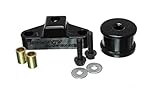
- Feel the difference, instantly with the PERRIN Shifter Stop. Remove loose and sloppy shift gate feel within minutes--no special tools required.
- FITS: SUBARU WRX 2015-17, 2018-20 CrossTrek, 2014+ Forester Legacy / Outback 2010-15
- Easy to install! Typically in less than 30 minutes!
- 5-year warranty (See details within product packaging)
- Fit Type: Vehicle Specific
- Package Dimensions: 13.462 H x 8.382 L x 9.652 W (centimetres)
- Country of Origin : United States
- Package Weight: 0.249 kilograms
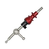
- 35% Shorter Shifts than Stock
- Offering the Shortest Shifts on the market for the 2015-25 WRX
- Replaces your OEM shifter and reverse lockout with no additional modifications
- Anodized Reverse Lockout for vibrant color and durability
- Machined from 6061 aluminum and 304 stainless steel. Made in the USA
SEOCONTENT-START
Bulletin Number: 16-112-18R; Revised 08/14/23 Page 1 of 11 NUMBER: 16-112-18R DATE: 03/15/18 REVISED: 08/14/23 APPLICABILITY: 2015-2018MY Legacy and Outback 2012-2018MY Impreza 2013-2018MY Crosstrek 2014-2018MY Forester 2015-2018MY WRX SUBJECT: Ignition Key Sticking / Design Change to CVT Shifter / Selector Lever Components CAUTION: VEHICLE SERVICING PERFORMED BY UNTRAINED PERSONS COULD RESULT IN SERIOUS INJURY TO THOSE PERSONS OR TO OTHERS. Subaru Service Bulletins are intended for use by professional technicians ONLY. They are written to inform those technicians of conditions that may occur in some vehicles, or to provide information that could assist in the proper servicing of the vehicle. Properly trained technicians have the equipment, tools, safety instructions, and know-how to do the job correctly and safely. If a condition is described, DO NOT assume that this Service Bulletin applies to your vehicle, or that your vehicle will have that condition. Subaru of America, Inc. is ISO 14001 Compliant ISO 14001 is the international standard for excellence in Environmental Management Systems. Please recycle or dispose of automotive products in a manner that is friendly to our environment and in accordance with all local, state and federal laws and regulations. Continued… INTRODUCTION: This bulletin announces a design change to the CVT select lever (shifter) mechanism in response to isolated customer concerns of not being able to remove the key from the ignition switch when the vehicle is in Park. The cause is contamination of the Park-Range switch internal components. PRODUCTION CHANGE INFORMATION: The new select lever components were incorporated into production as per the table below: Vehicle / Model Starting VIN Legacy J*017478 Outback J*245513 Impreza J*605062 Crosstrek J*712211 Forester J*441815 WRX J*808100 PART INFORMATION: IMPORTANT NOTES: • The term PLATE-GUIDE B refers to the Park-Range switch which is a serviceable part of the select lever assembly on all models listed above EXCEPT Legacy and Outback. See the illustrations provided below for more details. • For Legacy and Outback, the guide plate (GUIDE-PLATE A) must be replaced if the Park- Range switch is found to be faulty. SERVICE BULLETIN ATTENTION: GENERAL MANAGER q PARTS MANAGER q CLAIMS PERSONNEL q SERVICE MANAGER q IMPORTANT – All Service Personnel Should Read and Initial in the boxes provided, right. ©2018 Subaru of America, Inc. All rights reserved. Bulletin Number: 16-112-18R; Revised 08/14/23 Page 2 of 11 Continued… Description Part Number Applicability PLATE-GUIDE B 35122FJ033 2012-2016MY Impreza 2013-2017MY Crosstrek 2014-2018MY Forester 2015-2018MY WRX 35122AJ162 2018MY Crosstrek 35122FL00B 2017-2018MY Impreza CLAMP 35164AJ000 1-Time Use items, must be replaced whenever installing PLATE-GUIDE B on 35164AJ010 above models, 1 of each required. PLATE-GUIDE A 35192AL00A 2015-2018MY Legacy & Outback For Legacy and Outback: For all other models listed: SERVICE PROCEDURE / INFORMATION: NOTE: The diagnostics below were previously supplied in the June 2017 issue of TIPS. • After confirming the customer concern of not being able to remove the key from the ignition switch, check the following PID for Key lock solenoid output (Figure 1 below) in the Body Integrated Unit (BIU) current data display. Bulletin Number: 16-112-18R; Revised 08/14/23 Page 3 of 11 • If the Key lock solenoid output is displayed as Lock, the next step in diagnosis should be to check the following PID (Figure 2 below). • P SW is the park range switch, located in the AT shifter assembly. If the shifter is in the Park position and this PID remains OFF, suspect an issue with either the park range switch or the related wiring. Check for drink spills, previous interior repairs, modifications and the shift lever position itself. Troubleshooting procedures can be found in the applicable Service Manual under the AT Shift Lock Control System > KEY INTERLOCK CANNOT BE LOCKED OR RELEASED. After diagnosis has confirmed the Park-Range switch to be faulty, either: a) Replace the SELECT LEVER GUIDE-PLATE A (on Legacy and Outback models) or, b) Replace the Park-Range switch (PLATE-GUIDE B) following the Select Lever disassembly / assembly procedure in the applicable Service Manual. IMPORTANT TIP: After removing the shift knob there will be a white plastic rod / plunger protruding from the top of the chrome lever. Use a permanent marker and mark its position as shown in the photo so it can be put back in the same place during reassembly. The bottom end has a notch in it which must be in the correct position for proper operation of the mechanism. After Select Lever reassembly is complete, be sure to confirm the following: • the combination meter indicator matches the select lever position when changing from “P” range to “D” range • the select lever position and indicator match each other • the select lever operates smoothly from “P” to “D” and back to “P” range • the ignition key can be removed from the ignition lock when the vehicle is in Park. Continued… Bulletin Number: 16-112-18R; Revised 08/14/23 Page 4 of 11 Continued… GUIDE PLATE A / LEGACY & OUTBACK MODELS PART INFORMATION: Guide Plate Kit P.N. #35192AL00A SERVICE PROCEDURE: Guide Plate Removal for Legacy & Outback NOTE: Refer to the applicable Service Manual and review: General Description > Repair Contents > Action required before & after Battery Disconnect. Additionally, record any stored seat position(s) before proceeding. Relearn any seat position memory after work is complete. If the power rear gate (PRG) height has been customized, that position must also be noted and relearned. STEP 1) Engage the parking brake and remove the following parts by following the applicable Service Manual. A. Front console cover assembly B. Console box C. Left and right front console side cover assemblies Refer to: EXTERIOR/INTERIOR TRIM > Console Box > REMOVAL STEP 2) CAREFULLY disconnect the negative battery terminal while supporting the sensor with the other hand as outlined in the applicable Service Manual under: STARTING/CHARGING SYSTSEMS > Battery Sensor. STEP 3) Disconnect the harness connector from the gear selector lever. Bulletin Number: 16-112-18R; Revised 08/14/23 Page 5 of 11 STEP 4) Using a plastic trim tool, CAREFULLY release the connector mounting tab from the gear selector lever housing. Remove the harness from wiring security loops located on the gear selector lever shown below. STEP 5) CAREFULLY release the terminals #3 and #4 of the solenoid unit connector. Insert a suitable terminal removal tool from Snap-on® tool kit #SGTT110 or a flat-blade screwdriver (with a tip width of 1.3mm (0.05in) or less) into the connector and disengage the terminal holding tab while slightly pulling the wires from the connector. IMPORTANT NOTE: Terminal removal shown below. Continued… Bulletin Number: 16-112-18R; Revised 08/14/23 Page 6 of 11 Continued… STEP 6) Release the harness from wiring security loops located on the gear selector lever shown below. STEP 7) CAREFULLY remove the indicator cover by releasing the 4 tabs located on the sides. Use CAUTION when applying pressure to the tabs to prevent any damage. STEP 8) CAREFULLY remove the blind housing from the gear selector lever. DO NOT removed the indicator light terminals. Bulletin Number: 16-112-18R; Revised 08/14/23 Page 7 of 11 Continued… STEP 9) CAREFULLY release the terminals #5 and #6 of the indicator light connector. Insert a suitable terminal removal tool from Snap-on® tool kit #SGTT110 or a flat-blade screwdriver (with a tip width of 1.3mm (0.05in) or less) into the connector and disengage the terminal holding tab while slightly pulling the wires from the connector. STEP 10) Remove the clamp push nut located on the left rear section of the gear selector lever. IMPORTANT NOTE: The clamp push nut is a one-time use part. A new nut MUST be use during assembly. STEP 11) Remove the guide pin while applying downforce pressure to the guide plate. Bulletin Number: 16-112-18R; Revised 08/14/23 Page 8 of 11 Continued… STEP 12) Remove the guide plate by raising the rear section to disengage the holding claws located at the front of the plate housing. IMPORTANT NOTE: Use CAUTION to not damage or misplace the plunger rod or detent pin. STEP 13) CARFULLY release the terminals #1 and #2 of the “manual mode” switch. Release terminals #7 and #8 of the “Parking range” switch. Insert a suitable terminal removal tool from Snap-on® tool kit #SGTT110 or a flat-blade screwdriver (with a tip width of 1.3mm (0.05in) or less) into the connector and disengage the terminal holding tab while slightly pulling the wires from the connector. NOTE: There is no polarity of these terminals. The MUST STILL be connected to match the original position to prevent any stress on the wiring. Bulletin Number: 16-112-18R; Revised 08/14/23 Page 9 of 11 Continued… INSTALLATION: STEP 1) Apply the supplied grease to the required areas (A,B, and C) shown below. Apply one pack of grease to section A. Apply ½ pack of grease to sections B and C. CAUTION: DO NOT apply grease to the switches located inside the guide plate. STEP 2) Install the new guide plate and reassemble the gear selector lever in the reverse order of disassembly. CAUTION: Shift the gear selector lever into the neutral position prior to installation to prevent any damage to the switches. IMPORTANT NOTE: Whenever reconnecting the ground cable terminal to the battery sensor, torque to 7.5Nm (5.5ft.-lbs. or 66inch-lbs.) while supporting the sensor with the other hand as outlined in the applicable Service Manual under: STARTING/CHARGING SYSTEMS > Battery Sensor. Bulletin Number: 16-112-18R; Revised 08/14/23 Page 10 of 11 Continued… INSTALLATION TIPS: 1. Use a deep socket to install the clamp push nut. This will fully seat the clamp push nut against the gear selector lever housing. 2. Confirm the blind is installed in the correctly within the guide rails. • Inspect the highlighted areas after the blind is installed to ensure proper alignment. • Operate the gear selector lever and confirm the indicated gear position matches the actual gear position. • Confirm the “door open” audio indicator operates when the door is open with the gear selector lever in the “Park” position when the ignition is switched OFF. WARRANTY / CLAIM INFORMATION: IMPORTANT NOTE: If the vehicle falls within the 1-year grace period, you will need to submit a warranty authorization request using the coding below and “Concern documented prior to warranty expiration” as your Authorization reason. PARK-RANGE SWITCH WARRANTY EXTENSION ONLY Labor Description Labor Operation # Labor Time Fail Code A/T SHIFT LOCK TESTING B308-001 0.4 MDH-43 GUIDE PLATE R&R (LEGACY & OUTBACK ONLY) C308-166 0.5 PARK-RANGE SWITCH R&R, (ALL OTHER MODELS LISTED IN THIS BULLETIN) C308-161 1.1 Bulletin Number: 16-112-18R; Revised 08/14/23 Page 11 of 11 IMPORTANT REMINDERS: • SOA strongly discourages the printing and/or local storage of service information as previously released information and electronic publications may be updated at any time. • Always check for any open recalls or campaigns anytime a vehicle is in for servicing. • Always refer to STIS for the latest service information before performing any repairs.
**************************************************************************************************************
SEOCONTENT-END
This product presentation was made with AAWP plugin.