
NHTSA ID Number: 10237306
Manufacturer Communication Number: 07-220-23
Summary
This service information bulletin announces the diagnostic procedures to be used when DTCs P0AA649 (Hybrid/EV Battery Voltage System Isolation Internal Electronic Failure) & P1C7E49 (Hybrid/EV Battery Voltage System Isolation (Transaxle Area) Internal Electronic Failure) are detected by the Powertrain Control Unit (PCU).
NUMBER: 07-220-23
DATE: 05/16/23
| APPLICABILITY: | 2019-23MY Crosstrek PHEV |
| SUBJECT: | Diagnostic Procedures / DTCs P0AA649 & P1C7E49 |
INTRODUCTION:
This service information bulletin announces the diagnostic procedures to be used when DTCs
P0AA649 (Hybrid/EV Battery Voltage System Isolation Internal Electronic Failure) & P1C7E49 (Hybrid/EV Battery Voltage System Isolation (Transaxle Area) Internal Electronic Failure) are detected by the Powertrain Control Unit (PCU). Follow the procedures outlined in this bulletin if the described DTCs are encountered.
DIAGNOSTIC PROCEDURE / INFORMATION:

| STEP 1: Check Inverter with converter assembly | |
| Procedure | 1. Confirm the service plug is disconnected.
2. Visually inspect the wiring for any physical damage. 3. Disconnect the inverter/converter assembly from Power Cable. (*1) 4. Using a megohmmeter (500 V range), measure the resistance between connector (HV99) terminal and chassis ground. (*1) Replace the inverter/converter, inverter/converter motor cable, and Power Cable ONLY if water intrusion or rust caused by water intrusion are found on the inverter/converter assembly side. |
| Check
List | ■For Motor
(HV99) U2-chassis ground (HV99) V2-chassis ground (HV99) W2-chassis ground Are the resistances 1.8 MΩ or more?
■For Generator (HV99) U1-chassis ground (HV99) V1-chassis ground (HV99) W1-chassis ground Are the resistances 1.8 MΩ or more? |
| YES | Go to STEP 3. |
| NO | Go to STEP 2. |
| STEP 2: Check the motor cable of Inverter with converter | |
| Procedure | 1. Confirm the service plug is disconnected.
2. Visually inspect the wiring for any physical damage. 3. Remove the inverter/converter assembly from the vehicle. Refer to STIS: Body & Electrical/WIRING SYSTEM >HYBRID ELECTRIC VEHICLE > Inverter and Converter Assembly> Removal 4. Remove the Inverter/converter assembly motor cable cover. (*2) 5. Remove the motor cable from Inverter with converter. (*2) 6. Using a megohmmeter (500 V range), measure the resistance between connector (HV99) terminal of motor cable of inverter/converter and motor cable case (metal part).  |
| Check
List | (*2) Replace the inverter/converter, and inverter/converter motor cable ONLY if water intrusion is found inside the cover or motor cable.
■For Motor (HV99) U2-motor cable case (metal part) (HV99) V2-motor cable case (metal part) (HV99) W2-motor cable case (metal part) Are the resistances 100 MΩ or more?
■For Generator (HV99) U1-motor cable case (metal part) (HV99) V1-motor cable case (metal part) (HV99) W1-motor cable case (metal part) Are the resistances 100 MΩ or more? |
| YES | Replace inverter with converter |
| NO | Replace inverter with converter motor cable. |
| STEP 3: Check the Power Cable (for Motor) with transmission connected | |
| Procedure | 1. Confirm the service plug is disconnected.
CAUTION: Never turn to READY ON with Service plug removed to prevent faults. 2. Visually inspect the wiring for any physical damage. 3. Turn to READY OFF (Turn the ignition on). NOTE: Since other DTCs are memorized when turning the ignition on with the service plug removed, clear the memory of DTCs after inspection. 4. Check that ATF oil temperature is less than 50 Celsius (122 Fahrenheit) by using Subaru Select Monitor: Subaru Select Monitor > [P-HEV hybrid powertrain control] > Data Monitor. 5. Using a megohmmeter (500 V range), measure the resistance between connector (HV99) terminal of Power Cable (For Motor) (on inverter/converter assembly side) and chassis ground and shield line ground. |
| Check
List | (HV99) U2-chassis ground and shield line ground
(HV99) V2-chassis ground and shield line ground (HV99) W2-chassis ground and shield line ground Are the resistances 44 MΩ or more? (CONFIRM the ATF oil temperature less than 50 Celsius (122 Fahrenheit)). Reference EXAMPLE for chassis ground: 
Reference EXAMPLE for shield line ground: 
|
| YES | Go to STEP 4. |
| NO | Go to STEP 5. |
| STEP 5: Check the Power Cable (for Motor) without Transmission connected | |
| Procedure | 1. Confirm the service plug is disconnected.
2. Visually inspect the wiring for any physical damage. 3. Disconnect the Power Cable from Transmission Assy. 4. Using a megohmmeter (500 V range), measure the resistance between connector (HV99) terminal of Power Cable (for Motor) (on inverter/converter assembly side) and chassis ground and shield line ground. |
| Check
List | (HV99) U2- chassis ground and shield line ground (HV99) V2- chassis ground and shield line ground (HV99) W2- chassis ground and shield line ground
Are the resistances 100 MΩ or more? |
| YES | Go to STEP 6. |
| NO | Replace the Power Cable. |
| STEP 4: Check the Power Cable (for Generator) with transmission connected | |
| Procedure | 1. Confirm the service plug is disconnected.
2. Visually inspect the wiring for any physical damage. 3. Using a megohmmeter (500 V range), measure the resistance between connector (HV99) terminal of Power Cable (for Generator) (on inverter/converter assembly side) and chassis ground and shield line ground. |
| Check
List | (HV99) U1- chassis ground and shield line ground (HV99) V1- chassis ground and shield line ground (HV99) W1- chassis ground and shield line ground
Are the resistances 100 MΩ or more? |
| YES | Normal operation at this time. |
| NO | Go to STEP 5. |
| STEP 6: Check the Power Cable (for Generator) | |
| Procedure | 1. Confirm the service plug is disconnected.
2. Visually inspect the wiring for any physical damage. 3. Using a megohmmeter (500 V range), measure the resistance between connector (HV99) terminal of Power Cable (for Generator) (on inverter/converter assembly side) and chassis ground and shield line ground. |
| Check
List | (HV99) U1- chassis ground and shield line ground (HV99) V1- chassis ground and shield line ground (HV99) W1- chassis ground and shield line ground
Are the resistances 100 MΩ or more? |
| YES | Replace the Transmission Assembly. |
| NO | Replace the Power Cable. |
SERVICE PROCEDURE INFORMATION:
There have been no changes made to the work procedures. Always refer to the applicable Service Manual and review the full requirements of the repair being performed. The Service Manual procedures contain information critical to performing an effective repair the first time, every time. This includes but is not limited to important SAFETY precautions, proper inspection criteria, necessary special tools, required processes and related one-time-use parts needed for a complete and lasting repair.
5 Affected Products
Vehicle
| MAKE | MODEL | YEAR |
| SUBARU | CROSSTREK HYBRID | 2019-2023 |
1 Associated Document
Manufacturer Communications
NUMBER: 07-220-23
DATE: 05/16/23
MC-10237306-0001.pdf 718.222KB
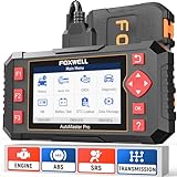
- [Easy to Use—Work Out of the Box] + [FOXWELL 2026 New Version] FOXWELL NT604 Elite scan tool is the 2026 new version from FOXWELL, designed for car owners who want to figure out the cause of issues before fixing car problems by scanning common systems like ABS, SRS, engine, and transmission. The NT604 Elite obd2 scanner diagnostic tool comes with the latest software—no need to waste time downloading software first. Plug the scanner into the OBDII port with OBDII cable to start the diagnosis.
- [Affordable] + [Reliable Car Health Monitor] Will you be confused what happens when the warning light of ABS/SRS/transmission/check engine flashes? Instead of taking your cars to dealership, this FOXWELL scanner will help you do a thorough scanning and detection for your cars and pinpoint the root cause. Note:The device is a diagnostic tool, not a repair tool. To turn off a warning light, you must first physically repair the issue causing it. Only then can the scanner be used to clear the corresponding fault code.
- [5 in 1 Car Diagnostic Scanner] Compared with obd scanners (50-100), NT604 Elite code scanner not only includes their OBDII diagnosis but also serves as ABS/SRS scanner, transmission and check engine code reader. When it’s an odb2 scanner, you can use it to check if your car is ready for annual test through I/M readiness menu. In addition, live data stream, built-in DTC library, data play back and print, all these features are a big plus for it. Note: doesn't support maintenance functions like reset or relearn. For the SRS system, NT604 Elite can read and clear common fault codes not caused by a crash, but crash/collision data cannot be cleared.
- [Fantastic AUTOVIN] + [No extra software fee] Through the AUTOVIN menu, this NT604 Elite car scanner allows you to get your V-IN and vehicle info rapidly, no need to take time to find your V-IN and input one by one. What's more, the NT604 Elite ABS SRS scanner supports 60+ car brands from worldwide (America/Asia/Europe). You don’t need to pay extra software fee. AUTOVIN may not work on some older vehicles or certain vehicle brands. If AUTOVIN fails, please input the vin code manually or go to the Diagnostic Menu to select your vehicle model.
- [Solid protective case KO plastic carrying bag] + [Lifetime update] Almost all same price-level car scanner diagnostic tool only offers plastic bag to hold the scanner.However, NT604 Elite automotive scanner is equipped with solid protective case, preventing your obd2 scanner from damage. Then you don’t need to pay extra money to buy a solid toolbox.

- 【Reset ABS/SRS/Transmission/Engine Lights】 More than an check engine code reader, OBDMATE OM901 obd2 scanner performs comprehensive diagnostics for the 4 most-used systems (ABS/SRS/Engine/Transmission). It quickly clears fault codes, turns off warning lights, read data stream and auto VIN.
- 【3.5" Handheld Scanner with 4 System Diagnose】 3.5" Super large TFT screen equipped displays an intuitive menu and clear readings of various sensors from ABS, SRS, ECM and TCM
 systems. It arrived with a silicone protective case and hard-shell carrying case, ensuring long-lived durability and drop resistance. The car diagnostic tool is plug-to-play designed, plug it and get diagnosis started without any batteries or updates required.
 - 【One-Click I/M Readines&Full OBD2 Functions】 Press F1 to get an intuitive corloured form about whether various emissions-related systems on the vehicle are operating properly. Help you get smog-check ready quickly. OM901 car scanner supports all essential OBD2 functions you need: read & clear codes, view freeze frame, read I/M readiness, retrieve VIN, live data stream (with graphing display), O2 sensor test, onboard monitoring mode, and EVAP leak test.
- 【Battery Voltage Check&DLC Pin Test】 It allows you to monitor battery health by testing current battery voltage. Plus, this obd2 diagnostic tool features DLC 16-PIN test to check current voltage of every pin.
- 【Automotive Scanner Diagnostic Kit】 The package comes with 1 car scanner, 1 USB-type c cable, 1 hard storage bag and 1 user manual(en). Free to update without any hidden fees. 5 languanges available in setting including English, French, Italian, German and Espanish. Valuable and Portable, making it a great tool kit for car owners, DIY enthusiasts, and professional mechanics.
 systems. It arrived with a silicone protective case and hard-shell carrying case, ensuring long-lived durability and drop resistance. The car diagnostic tool is plug-to-play designed, plug it and get diagnosis started without any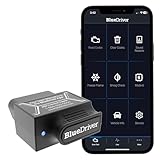
- [Diagnose Like a Pro] BlueDriver Pro is a professional OBD2 scanner and diagnostic tool that helps you scan, understand, and clear vehicle trouble codes with confidence. Turn your phone into a powerful car diagnostic scanner—no guesswork, no unnecessary repairs.
- [Read and Clear More Codes Than Ever] Read and clear more codes than basic car code readers. Access enhanced diagnostics for Check Engine, ABS, SRS, Airbag, TPMS, Transmission.
- [Verified Fixes and Real-Time Data] Get unlimited, technician-verified repair reports matched to your VIN, with definitions, causes, and confirmed fixes. Monitor live vehicle data as you drive, view freeze frames, check smog readiness, and analyze Mode 6 test results.
- [Wireless & Bluetooth Enabled] - Say goodbye to wires. BlueDriver connects with Bluetooth via your phone/tablet to a sensor that plugs into your car's OBDII port. Get all of the capabilities of an expensive code reader & scan tool without any annoying wires.
- [Broad Make & Model Coverage] Strong support for GM, Ford, Stellantis (RAM, Jeep, Chrysler), Toyota, Honda, Nissan, Mazda, Subaru, Hyundai, Mercedes-Benz, BMW, and VW.
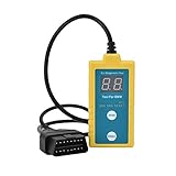
- ✔️【Professional SRS Reset for 1994-2003 BMW】 Designed specifically for classic BMW models (1994-2003). This B800 scanner reads & clears SRS airbag fault codes, turns off the warning light, and saves you a costly dealer visit. Confirmed compatible with: E36, E46 (EXCEPT 2001 330i), E34, E38, E39, Z3, and X5 (E53). NOT compatible with any BMW built before 1994 or after 2003.
- ✔️【Important: Two Different Connection Ports – Read Before Use】 To avoid “not working” issues, please note: For 1994–2000 BMWs (most E36, E34, Z3, early E39), the SRS diagnostic port is a round 20-pin connector under the hood. You MUST use the included 16-pin to 20-pin adapter cable. For 2000–2003 models (late E46, E39, X5), use the standard OBD-II port inside the cabin. Incorrect connection is the #1 reason for “incompatibility” reports.
- ✔️【Read & Clear Fault Codes in Minutes】 Quickly diagnose why your SRS light is on. The scanner accurately reads fault codes from airbag and seatbelt pretensioner systems. With one button press, clear the codes and reset the SRS warning light in seconds. No expensive dealer tools needed.
- ✔️【User-Friendly for DIYers – No Mechanic Required】 Easy operation with an intuitive button layout: ‘Enter’ to confirm, ‘Scroll’ to navigate. The clear LCD screen shows results instantly. Includes a step-by-step manual (revised for clarity) to guide you through the entire reset process.
- ✔️【Reliable Support with 1-Year Warranty】 We stand behind the quality of our B800 scanner. It comes with a 1-Year Hassle-Free Warranty. If you have any questions or need support, please contact us with your Order ID, and our dedicated team will assist you promptly.
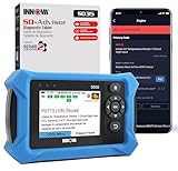
- OBD2 SCANNER FOR ALL SYSTEMS – The INNOVA SD35 is a tablet-based OBD2 scanner designed for advanced diagnostics. Read and clear check engine light, ABS, SRS, and TPMS codes, plus test your car battery and alternator to prevent unexpected failures. Vehicle coverage may vary. Please use Innova’s Coverage Checker to verify compatibility.
- ALL-SYSTEM DIAGNOSTICS & LIVE DATA – Unlike basic code readers, this OBD2 scanner for all vehicles scans engine, transmission, ABS, SRS, and more. Get real-time live data, including RPM, fuel trims, temperature readings, and oxygen sensor performance.
- OBD2 TABLET WITH USER-FRIENDLY INTERFACE – This automotive scan tool features a high-resolution display, making vehicle diagnostics faster and easier.
- ADVANCED TPMS, OIL RESET & SERVICE FUNCTIONS – Perform TPMS sensor checks, oil light reset, and other service resets with ease This professional diagnostic tool provides comprehensive vehicle maintenance capabilities in one device.
- WIDE VEHICLE COVERAGE (1996 & NEWER CARS & TRUCKS) – This OBD2 scanner Bluetooth tablet is compatible with Toyota, Ford, Honda, Chevrolet, Nissan, Dodge, and more. However, feature coverage may vary. Please use Innova's Coverage Checker to verify coverage.
SEOCONTENT-START
Bulletin Number: 07-220-23; Date: 05/16/23 Page 1 of 6 SERVICE BULLETIN Continued… CAUTION: VEHICLE SERVICING PERFORMED BY UNTRAINED PERSONS COULD RESULT IN SERIOUS INJURY TO THOSE PERSONS OR TO OTHERS. Subaru Service Bulletins are intended for use by professional technicians ONLY. They are written to inform those technicians of conditions that may occur in some vehicles, or to provide information that could assist in the proper servicing of the vehicle. Properly trained technicians have the equipment, tools, safety instructions, and know-how to do the job correctly and safely. If a condition is described, DO NOT assume that this Service Bulletin applies to your vehicle, or that your vehicle will have that condition. Subaru of America, Inc. is ISO 14001 Compliant ISO 14001 is the international standard for excellence in Environmental Management Systems. Please recycle or dispose of automotive products in a manner that is friendly to our environment and in accordance with all local, state and federal laws and regulations. NUMBER: 07-220-23 DATE: 05/16/23 APPLICABILITY: 2019-23MY Crosstrek PHEV SUBJECT: Diagnostic Procedures / DTCs P0AA649 & P1C7E49 INTRODUCTION: This service information bulletin announces the diagnostic procedures to be used when DTCs P0AA649 (Hybrid/EV Battery Voltage System Isolation Internal Electronic Failure) & P1C7E49 (Hybrid/EV Battery Voltage System Isolation (Transaxle Area) Internal Electronic Failure) are detected by the Powertrain Control Unit (PCU). Follow the procedures outlined in this bulletin if the described DTCs are encountered. DIAGNOSTIC PROCEDURE / INFORMATION: ATTENTION: GENERAL MANAGER q PARTS MANAGER q CLAIMS PERSONNEL q SERVICE MANAGER q IMPORTANT – All Service Personnel Should Read and Initial in the boxes provided, right. ©2023 Subaru of America, Inc. All rights reserved. Bulletin Number: 07-220-23; Date: 05/16/23 Page 2 of 6 Continued… STEP 1: Check Inverter with converter assembly Procedure 1. Confirm the service plug is disconnected. 2. Visually inspect the wiring for any physical damage. 3. Disconnect the inverter/converter assembly from Power Cable. (*1) 4. Using a megohmmeter (500 V range), measure the resistance between connector (HV99) terminal and chassis ground. (*1) Replace the inverter/converter, inverter/converter motor cable, and Power Cable ONLY if water intrusion or rust caused by water intrusion are found on the inverter/converter assembly side. Check List ■For Motor (HV99) U2-chassis ground (HV99) V2-chassis ground (HV99) W2-chassis ground Are the resistances 1.8 MΩ or more? ■For Generator (HV99) U1-chassis ground (HV99) V1-chassis ground (HV99) W1-chassis ground Are the resistances 1.8 MΩ or more? YES Go to STEP 3. NO Go to STEP 2. Bulletin Number: 07-220-23; Date: 05/16/23 Page 3 of 6 Continued… STEP 2: Check the motor cable of Inverter with converter Procedure 1. Confirm the service plug is disconnected. 2. Visually inspect the wiring for any physical damage. 3. Remove the inverter/converter assembly from the vehicle. Refer to STIS: Body & Electrical/WIRING SYSTEM >HYBRID ELECTRIC VEHICLE > Inverter and Converter Assembly> Removal 4. Remove the Inverter/converter assembly motor cable cover. (*2) 5. Remove the motor cable from Inverter with converter. (*2) 6. Using a megohmmeter (500 V range), measure the resistance between connector (HV99) terminal of motor cable of inverter/converter and motor cable case (metal part). Check List (*2) Replace the inverter/converter, and inverter/converter motor cable ONLY if water intrusion is found inside the cover or motor cable. ■For Motor (HV99) U2-motor cable case (metal part) (HV99) V2-motor cable case (metal part) (HV99) W2-motor cable case (metal part) Are the resistances 100 MΩ or more? ■For Generator (HV99) U1-motor cable case (metal part) (HV99) V1-motor cable case (metal part) (HV99) W1-motor cable case (metal part) Are the resistances 100 MΩ or more? YES Replace inverter with converter NO Replace inverter with converter motor cable. Bulletin Number: 07-220-23; Date: 05/16/23 Page 4 of 6 Continued… STEP 3: Check the Power Cable (for Motor) with transmission connected Procedure 1. Confirm the service plug is disconnected. CAUTION: Never turn to READY ON with Service plug removed to prevent faults. 2. Visually inspect the wiring for any physical damage. 3. Turn to READY OFF (Turn the ignition on). NOTE: Since other DTCs are memorized when turning the ignition on with the service plug removed, clear the memory of DTCs after inspection. 4. Check that ATF oil temperature is less than 50 Celsius (122 Fahrenheit) by using Subaru Select Monitor: Subaru Select Monitor > [P-HEV hybrid powertrain control] > Data Monitor. 5. Using a megohmmeter (500 V range), measure the resistance between connector (HV99) terminal of Power Cable (For Motor) (on inverter/converter assembly side) and chassis ground and shield line ground. Check List (HV99) U2-chassis ground and shield line ground (HV99) V2-chassis ground and shield line ground (HV99) W2-chassis ground and shield line ground Are the resistances 44 MΩ or more? (CONFIRM the ATF oil temperature less than 50 Celsius (122 Fahrenheit)). Reference EXAMPLE for chassis ground: Reference EXAMPLE for shield line ground: YES Go to STEP 4. NO Go to STEP 5. Bulletin Number: 07-220-23; Date: 05/16/23 Page 5 of 6 Continued… STEP 4: Check the Power Cable (for Generator) with transmission connected Procedure 1. Confirm the service plug is disconnected. 2. Visually inspect the wiring for any physical damage. 3. Using a megohmmeter (500 V range), measure the resistance between connector (HV99) terminal of Power Cable (for Generator) (on inverter/converter assembly side) and chassis ground and shield line ground. Check List (HV99) U1- chassis ground and shield line ground (HV99) V1- chassis ground and shield line ground (HV99) W1- chassis ground and shield line ground Are the resistances 100 MΩ or more? YES Normal operation at this time. NO Go to STEP 5. STEP 5: Check the Power Cable (for Motor) without Transmission connected Procedure 1. Confirm the service plug is disconnected. 2. Visually inspect the wiring for any physical damage. 3. Disconnect the Power Cable from Transmission Assy. 4. Using a megohmmeter (500 V range), measure the resistance between connector (HV99) terminal of Power Cable (for Motor) (on inverter/converter assembly side) and chassis ground and shield line ground. Check List (HV99) U2- chassis ground and shield line ground (HV99) V2- chassis ground and shield line ground (HV99) W2- chassis ground and shield line ground Are the resistances 100 MΩ or more? YES Go to STEP 6. NO Replace the Power Cable. Bulletin Number: 07-220-23; Date: 05/16/23 Page 6 of 6 STEP 6: Check the Power Cable (for Generator) Procedure 1. Confirm the service plug is disconnected. 2. Visually inspect the wiring for any physical damage. 3. Using a megohmmeter (500 V range), measure the resistance between connector (HV99) terminal of Power Cable (for Generator) (on inverter/converter assembly side) and chassis ground and shield line ground. Check List (HV99) U1- chassis ground and shield line ground (HV99) V1- chassis ground and shield line ground (HV99) W1- chassis ground and shield line ground Are the resistances 100 MΩ or more? YES Replace the Transmission Assembly. NO Replace the Power Cable. SERVICE PROCEDURE INFORMATION: There have been no changes made to the work procedures. Always refer to the applicable Service Manual and review the full requirements of the repair being performed. The Service Manual procedures contain information critical to performing an effective repair the first time, every time. This includes but is not limited to important SAFETY precautions, proper inspection criteria, necessary special tools, required processes and related one-time-use parts needed for a complete and lasting repair. IMPORTANT REMINDERS: • SOA strongly discourages the printing and/or local storage of service information as previously released information and electronic publications may be updated at any time. • Always check for any open recalls or campaigns anytime a vehicle is in for servicing. • Always refer to STIS for the latest service information before performing any repairs.
**************************************************************************************************************
**************************************************************************************************************
SEOCONTENT-END
This product presentation was made with AAWP plugin.