| “This site contains affiliate links for which OEMDTC may be compensated” |
SUMMARY:
Subaru of America, Inc. (Subaru
 ) is recalling certain model year 2016-2017 Legacy and Outback vehicles manufactured February 29, 2016, to May 6, 2016.
The steering column on the affected vehicles may have been improperly machined, and as a result, turning the steering wheel may have no effect on the direction of the wheels.
CONSEQUENCE:
The loss of steering ability would increase the risk of a crash.
REMEDY:
Subaru will notify owners, and dealers will inspect the lot number on the steering column, replacing the steering column, as necessary, free of charge.
The recall began May 13, 2016.
Owners may contact Subaru customer service at 1-800-782-2783 or by visiting https://www.wtd65.service-campaign.com.
Subaru ’s number for this recall is WTD-65.
Note: Until the vehicles have been inspected, owners are advised not to drive their vehicles.
NOTES:
Owners may also contact the National Highway Traffic Safety Administration Vehicle Safety Hotline at 1-888-327-4236 (TTY 1-800-424-9153), or go to www.safercar.gov.
Check if your Subaru has a Recall
NUMBER: WTD-65
DATE: 06/08/16
NHTSA ID: 16V-292
| APPLICABILITY: | 2016-2017MY Legacy and Outback |
| SUBJECT: | Inspection and Repair Procedure for Stop Sale / Recall Campaign WTD-65: Steering Column |
SUBARU OF AMERICA, INC. has determined that a defect, which relates to motor vehicle safety, exists in certain 2016 and 2017 model year Legacy and Outback vehicles.
DESCRIPTION OF THE SAFETY RISK
The steering columns in these vehicles may not have been manufactured to specification. An incorrect tool setting during the manufacturing process may have resulted in improper machining of one of the steering column shafts. If this condition exists, turning the steering wheel may have no effect on the direction of the wheels, increasing the risk of a crash.
DESCRIPTION OF THE REMEDY
Subaru will inspect the lot number on the steering column to determine if it needs to be replaced. If replacement is necessary, a new steering column will be installed in the vehicle. The inspection and possible replacement will be performed at no cost to the customer.
OWNER NOTIFICATION
Subaru notified potentially affected vehicle owners by first class mail on May 13, 2016. A copy of the owner notification letter is included at the end of this bulletin.
AFFECTED VEHICLES
Not all vehicles in the VIN ranges listed below are affected by this campaign. Coverage for all affected vehicles must be confirmed by using the Vehicle Coverage Inquiry function on subarunet.com.
| Model Year | Models | Potentially Affected VIN Range (last 8 digits) |
|---|---|---|
| 2016 | Legacy | From G3045004 to G3059641 |
| 2016 | Outback | From G3307507 to G3346346 |
| 2017 | Legacy | From H3002001 to H3002024 |
| 2017 | Outback | From H3200001 to H3200048 |
RETAILER AFFECTED VIN LISTS
Each Subaru retailer has received an affected VIN list from their Zone Office. Vehicles were assigned based on the selling retailer information in Subaru
 ’s system. Retailers should use this information to contact owners to schedule this repair.
RETAILER PROGRAM RESPONSIBILITY
Any vehicles listed in a recall/campaign that are in retailer stock must be:
- Immediately identified.
- Tagged or otherwise marked to prevent their delivery or use prior to inspection and/or repair.
- Repaired in accordance with the repair procedures outlined in this Product Campaign Bulletin.
Retailers are to promptly perform the applicable service procedures to correct all affected vehicles in their inventory (used, demo & SSLP). Additionally, whenever a vehicle subject to this recall is taken into retailer inventory, or in for service, necessary steps should be taken to ensure the recall correction has been made before selling or releasing the vehicle.
Please be advised that it is a violation of Federal law for a dealer to deliver a new motor vehicle covered by a recall under a sale or lease until the defect is remedied. Therefore, any Authorized Subaru Retailer failing to perform the applicable service procedures to correct all affected vehicles in their inventory prior to the vehicle being placed in service may be subject to civil penalties of up to $6,000 per violation (i.e., for each vehicle), as provided in 49 CFR §578.6 and will also be in breach of the Subaru Retailer failing to perform the applicable service procedures to correct all affected vehicles in their inventory prior to the vehicle being placed in service may be subject to civil penalties of up to $6,000 per violation (i.e., for each vehicle), as provided in 49 CFR §578.6 and will also be in breach of the Subaru Dealer Agreement. Dealer Agreement. |
This Service Procedure provides an inspection method for identification of affected vehicles and if determined necessary, additional steps for replacing the steering column assembly.
INSPECTION PROCEDURE:
- Coverage for all affected vehicles must be confirmed by using the Vehicle Coverage Inquiry function on subarunet.com. This data is now available.
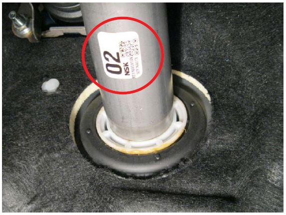
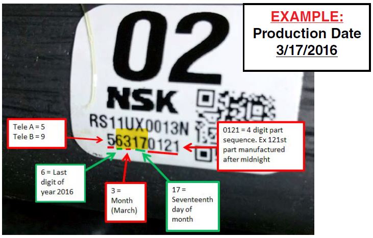
- Decode the lot number of the steering column using the illustration below.
- Affected steering columns will have a lot number label indicating the column was produced on or between 6228 (February 28, 2016) and 6416 (April 16, 2016), the steering column assembly must be replaced.
- If the lot number is illegible or otherwise cannot be determined, it must be noted on the repair order and the steering column assembly must be replaced.
- IMPORTANT: Always record the original lot number on the Repair Order even if it is outside the affected range. The ORIGINAL 4-digit lot number must also be entered in the Miscellaneous Detail field when submitting for claim reimbursement. If illegible, enter “ILLEGIBLE” in that field.
PARTS INFORMATION:
| Description | Part Number | Applicability | Quantity |
|---|---|---|---|
| COLUMN ASSEMBLY | 34500AL02A | Key Start | 1 |
| 34500AL03A | Push-Button Start | 1 | |
| BOLT (shear)* | 83140GA000 | All | 1 |
| WTD65 STEERING COLUMN SHAFT GASKET KIT** | SOA635143 | H-6 Models Only | 1 |
* One new shear bolt is included with the replacement steering column assembly.
**The SOA635143 kit is comprised of: 2- 44011AG040 and 1- 44022AA123 exhaust gaskets.
The SOA635143 kit will be shipped in a separate package concurrent with the steering column shipment.
SERVICE PROCEDURE:
After performing the Inspection procedure, if determined necessary, replace the steering column assembly following the Service Procedure provided below.
CAUTION: Refer to the “CAUTION” Section in the General Description portion of Airbag
System AB in the Body Section of the applicable Service Manual before handling any airbag module!
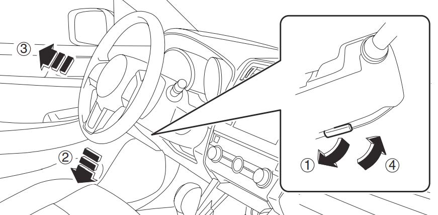
- Before proceeding with disassembly, unlock the tilt lever (1), adjust the tilt position of the steering column to the neutral position (2), adjust the telescopic position to the longest position (3) and place the lock lever back into the “locked” position (4).
- Record the customer’s radio station presets (and Navigation Favorites where applicable).
- Confirm the status of STARLINK Telematics lamp (where applicable). If the Green LED is on, press the RED SOS button to confirm an operator answers. Inform the Operator this is only a test.
- Disconnect the negative battery cable from the battery sensor and wait at least 60 seconds before proceeding.
- Using a plastic trim tool, remove the instrument panel end cover.
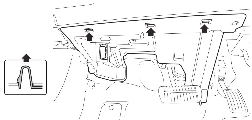
- Remove the data link connector, release the 3 retaining clips and remove the lower the instrument panel under cover.
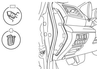
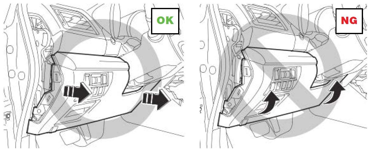
- Remove the necessary screws, release the claws and disconnect the harness connectors from the switches before CAREFULLY removing the instrument panel lower trim cover. NOTE: When removing the cover, pull it straight back toward you as shown in the illustration below. Do not pull / turn it upward as doing so may damage the retaining claws.
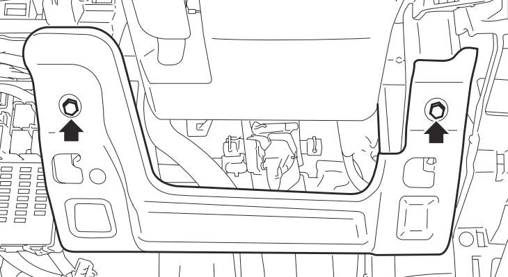
- Remove the knee guard.
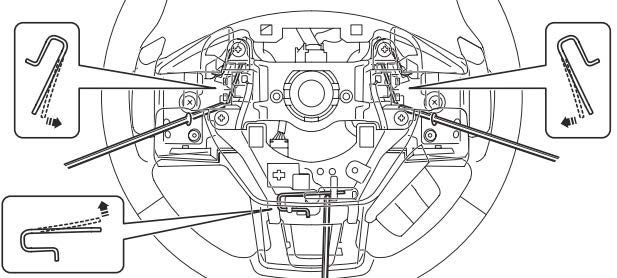
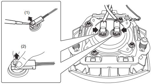
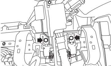
- With the wheels pointed straight ahead and using a hexagon wrench (or equivalent) wrapped with protective tape, locate and press on the snap pins to release the locks (three locations) securing the driver’s airbag module.
- CAREFULLY, release / remove the 2 airbag module harness connectors and set the module aside in a safe place.
- Using a steering wheel puller to prevent deforming the steering wheel, remove the steering wheel.
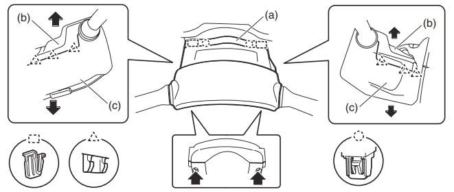
- Using a plastic trim tool, CAREFULLY release the retaining claws and remove the upper and lower steering column trim covers.
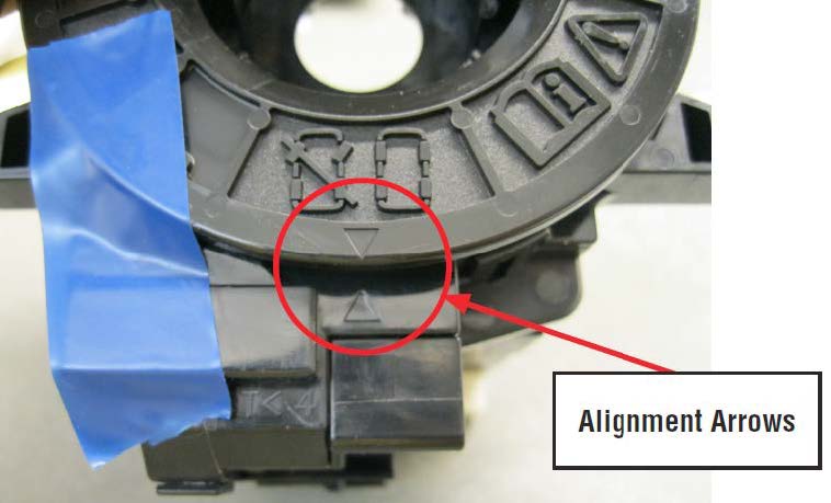
- After disconnecting all the wiring harness connectors, CAREFULLY remove the roll connector, steering angle sensor and the combination switch assemblies. IMPORTANT: Do not disturb the postion of the roll connector while removed from the steering column. As shown in the photo, use a piece of tape to keep it in alignment while removed.
IF the roll connector position is changed, the center position adjustment procedure provided below must be performed during reassembly.
Center Position Adjustment Procedure (Use only if roll connector position changed):
CAUTION: Do not rotate the roll connector to more than the specified number of turns. Otherwise, the roll connector internal wire may be broken. When determining the end stop, rotate the connector slowly without applying excessive force. Applying excessive force at the end stop may also break the internal wire.
- Confirm the front wheels are positioned in straight ahead direction.
- Rotate the roll connector counter-clockwise until it stops.
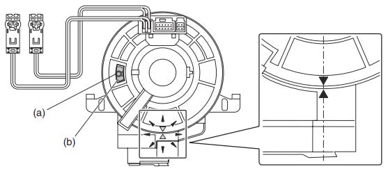
- Rotate the roll connector clockwise approximately 2.5 turns until the “Δ” marks are aligned.
NOTE: When the roll connector comes to the center position, the orange roller (b) can be seen from the sight glass (a) as shown below.
- Remove the engine under cover assembly.
- On H-6 models, remove the front exhaust pipe assembly following the procedure below:
- On H-4 models, proceed to “All Models Continued”
Front Pipe Removal Procedure for H-6 Models:
CAUTION: The exhaust system may be HOT.
- Disconnect the A/F and O2 Sensor wiring harness connectors.
- Remove the center exhaust pipe retaining nuts and spring bolts and separate the front exhaust pipe assembly from the center exhaust pipe. Retain the nuts, springs, and bolts for use at reassembly.
- Remove the nuts holding the front exhaust pipe onto the cylinder heads. Retain these nuts for use at reassembly.
- CAUTION: The front exhaust pipe assembly is heavy and the heat shield edges can be very sharp. Use appropriate personal protective equipment (PPE) and care while lifting.
- Remove the front exhaust pipe from vehicle as an assembly and set aside.
All Models Continued:
- Place an alignment mark on the lower universal joint shaft and steering rack input shaft.
- Remove the 2 retaining bolts and universal joint shaft assembly.
- Remove the 2 bolts securing the steering column assembly.
- CAREFULLY remove the steering column assembly taking special care to not dislodge the toe board grommet / bushing.
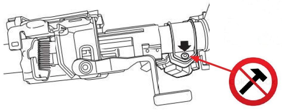
- Using a drill and screw extractor, remove the shear bolt securing the ignition lock to the steering column.
VERY IMPORTANT CAUTION: DO NOT apply any impact to the shear bolt when removing it (no hammers/chisels). Doing so will likely damage the Steering Lock Control Module (push start models).
- CAREFULLY Install the new steering column taking special care to not dislodge the toe board grommet / bushing. Tighten the 2 retaining bolts to 20 Nm (14.8 ft. lbs.).
- Transfer the ignition lock to the new steering column and secure with the new shear bolt.
- CAREFULLY reinstall the combination switch, roll connector, and steering angle sensor assemblies. REMINDER: If the position of the roll connector was disturbed, the center position adjustment procedure outlined above must be performed.
- Reconnect all the wiring harness connectors. CAUTION: On key-start vehicles, failure to reconnect the key lock solenoid connector will allow the ignition key to be removed from the ignition switch when the transmission shifter is not in park.
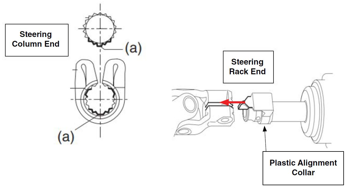
- Reinstall the universal joint shaft. Align the protrusion section (a) of the steering column shaft with the cutout (a) of the serration on the universal joint shaft as shown in the illustration on the left below. If not properly aligned, the upper bolt cannot be installed. Align the alignment mark on the steering rack end of the universal joint shaft with the mark on the steering rack input shaft and install the bolt but DO NOT TIGHTEN IT. The plastic alignment collar on the input shaft will slide into the split of the universal joint. Install the bolt and tighten to 24 Nm (17.7 ft. lbs.).
Tighten the other bolt (on the column end) to 24 Nm (17.7 ft. lbs.).
IMPORTANT: Always tighten the steering rack end retaining bolt first.
H-6 Models:
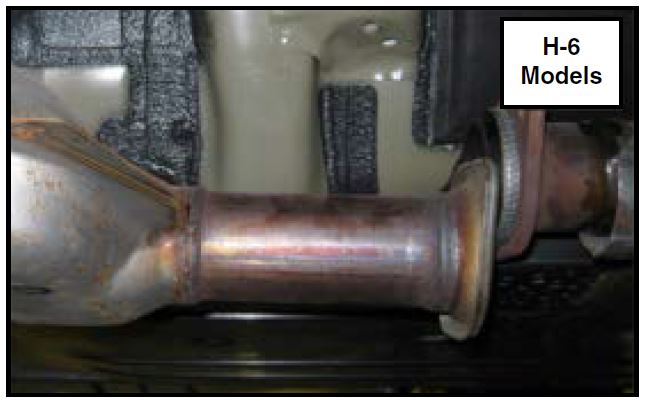
- Reinstall the front exhaust pipe assembly, always using new gaskets. Temporarily tighten the nuts holding the assembly to cylinder heads.
- Re-connect the center exhaust pipe, always using a new “donut” gasket. Torque the 2 spring bolt nuts to 18 Nm (13.3 ft. lbs.).
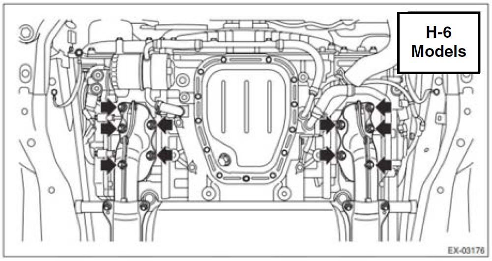
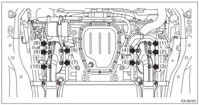
- Torque the nuts at the cylinder heads to 30 Nm (22.1 ft. lbs.) following the sequence shown in the illustrations below.
- Torque the 2 bolts holding the front pipe to the hanger bracket to 30 Nm (22.1 ft. lbs.).
- Reconnect the A/F and O2 Sensor wiring harness connectors.
All Models:
- Reinstall the engine under cover.
- Reinstall the knee guard and tighten the 2 bolts to 7 Nm (5.2 ft. lbs.).
- Reconnect the harness connectors to the switches and reinstall the instrument panel lower trim cover.
NOTE: Always make sure the harness connectors are plugged back into their proper positions and not into “dead” (unused) positions.
- Reinstall the lower instrument panel under cover.
- Reinstall the steering column trim covers.
- Reinstall the steering wheel and torque the retaining nut to 39 Nm (28.8 ft. lbs.).
- Reconnect the harness connectors and reinstall the driver’s airbag module.
- Reconnect the battery cable to the battery sensor. Torque the 12mm nut to 7.5 Nm (5.5 ft. lbs.).
- VERY IMPORTANT: ALWAYS confirm the steering column lock mechanism operates properly.
- If the steering column lock does not operate at all or
- If there is excess steering wheel freeplay (more than 1/4” up to approximately 2 ½”) when the steering column is locked, verify the proper column has been installed: an “02” on the label for key start models or an “03” on the label for push start models.
- Perform “VDC Sensor Midpoint Setting Mode” for the VDC system following the procedure below:
NOTE: The vehicle must be on a level surface with the wheels and steering wheel in the neutral (straight ahead) position.
- Connect the Subaru Select Monitor 4/DSTi to the data link connector. NOTE: For detailed operation procedures, refer to “Application Help”.
- Turn the ignition switch ON.
- On «Start» display, select «Diagnosis».
- On «Vehicle Specifications» display, input the target vehicle information (if not populated automatically) and select «Ok».
- On «Main Menu» display, select «Each System».
- On «Select List» display, select «Brake Control System» and select «Next».
- On «Select Function» display, select «Data Monitor».
- On «Data Monitor» display, select «Steering Angle Sensor», «Longitudinal G Sensor» and «Lateral G Sensor Output».
Confirm the steering angle sensor output value is within the range of following values:
- Model without EyeSight: –10 — 10 deg.
- Model with EyeSight: –2 — 2 deg.
- After confirming values are within range, select «Stop»
- Confirm the output values for the Longitudinal G Sensor and Lateral G Sensor are -2 to 2 m/s.
- From «Work Support», select «VSC (VDC) Centering Mode», and perform the setting procedure according to the procedure displayed on the Subaru Select Monitor screen.
NOTE: The applied model information found on the FMVSS label located at the base of the passenger side “B” pillar may be required.
- Reset the Auto-Up / Down feature of the power window system. Starting with the driver’s window fully open (down):
- Pull the switch up to close the window fully in steps (it will only close about 2” each time the switch is operated).
- Once the window is fully closed, pull up and hold the switch again for 1 second to complete the procedure.
- Repeat steps 1 and 2 for the passenger’s front window using the passenger window switch.
- Where applicable, confirm STARLINK returns automatically to the pre-repair status and an operator is contacted when pressing the RED SOS Inform the Operator this is only a test.
- Reset the customer’s radio station presets (and Navigation Favorites where applicable).
- Turn the ignition key ON, depress the brake pedal and place the transmission selector in D Confirm the ignition key cannot be removed. If the key can be removed, the key lock solenoid harness connector is most likely not properly connected.
- Drive the vehicle for 10 minutes and confirm there is no system malfunction, no warning light illumination and no DTCs set.
CLAIM REIMBURSEMENT AND ENTRY PROCEDURES:
Credit to perform this service campaign will be based on the submission of properly completed repair order information. Retailers may submit claims through Vehicle Claim Entry on subarunet.com.
NOTES:
- Non-SSLP Rentals will now be reimbursed at the retailer’s actual cost up to $50 per day exclusively for this WTD-65 campaign. Please enter the full cost of the non-SSLP rentals in the Sublet amount field on the RECALL claim.
- SSLP rentals are now reimbursed at $40 per day. Continue to use the Rental field for reimbursement on the RECALL claim.
- As examples:
- A 4-day Non-SSLP rental for $50 per day would be entered on the claim in the Sublet field for $200 and NO amount in the Rental field.
- A 4-day SSLP rental for $40 per day would continue to use the Rental field with an entry of $160 and do not enter any rental amount in the Sublet field.
- Sublet entries for Non-SSLP rental and off-site inspection must have comments detailing the amounts for each.
- For customers committing to purchase an affected unit, but needing immediate transportation while the unit is waiting for replacement parts, a rental car can be provided to the customer under the same terms listed above. Enter the rental amount on the RECALL claim.
- All documentation must be retained in accordance with current policies and procedures.
- In the event a customer obtained a rental vehicle on their own, rental reimbursement of up to $50 will also be allowed through the Customer Retailer Services Dept. (CRS).
- The ORIGINAL 4-digit lot number must also be entered in the Miscellaneous Detail field when submitting for claim reimbursement. If illegible, enter “ILLEGIBLE” in that field.
PARTS RETENTION:
For this recall only, once a claim has been submitted and APPROVED, the parts replaced to complete the repair may be scrapped.
NOTE: These parts will still show up on the monthly scrap report following the normal 30 days past credit cycle.
| Labor Description | Labor Operation # | Labor Time | Campaign Code | Claim Type |
|---|---|---|---|---|
| STEERING COLUMN- LOT# INSPECTION ONLY NO PART REPLACEMENT REQUIRED | A165-801 | 0.2 | WTD-65 | RC |
| STEERING COLUMN- LOT# INSPECTION & COLUMN ASSEMBLY REPLACEMENT (INCLUDES CENTERING THE STEERING WHEEL/TOE ADJUSTMENT WHERE REQUIRED) | A165-802 | 1.6 for H4 Models | ||
| A165-803 | 1.8 for H6 Models |
IMPORTANT REMINDERS:
- SOA strongly discourages the printing and/or local storage of service information as previously released information and electronic publications may be updated at any time.
- Always check for any open recalls or campaigns anytime a vehicle is in for servicing.
- Always refer to STIS for the latest service information before performing any repairs.
OWNER NOTIFICATION LETTER
| IMPORTANT SAFETY RECALL
This notice applies to the VIN identified in the address section printed below. |
Dear Subaru Owner:
This notice is sent to you in accordance with the National Traffic and Motor Vehicle Safety Act.
SUBARU OF AMERICA, INC. has decided that a defect, which relates to motor vehicle safety, exists in certain 2016 and 2017 model year Legacy and Outback vehicles.
You received this notice because our records indicate that you currently own one of these vehicles.
DESCRIPTION OF THE SAFETY RISK
The steering column in your vehicle may not have been manufactured to specification. An incorrect tool setting during the manufacturing process may have resulted in improper machining of one of the steering column shafts. If this condition exists, turning the steering wheel may have no effect on the direction of the wheels, increasing the risk of a crash.
Your vehicle is not safe to drive if this potential defect is present.
| WHAT YOU SHOULD DO
Please contact your retailer (dealer) as soon as possible to make arrangements to have your vehicle towed to their facility, at no cost to you, and inspected. If the inspection determines that the defect is not present, the vehicle will be safe to drive. If the defect is found, the steering column will be replaced. Please do not drive your car until it has been inspected and, if necessary, the recall repair has been performed. If you prefer to make alternative arrangements for having your vehicle towed to your retailer, you may contact the Subaru For your convenience, your retailer will provide you a loaner or rental vehicle at no cost until your car has been repaired. |
REPAIR
Subaru will inspect the lot number on the steering column in your vehicle to determine if it needs to be replaced. If replacement is necessary, a new steering column will be installed in your vehicle. The inspection and possible replacement will be performed at no cost to you.
HOW LONG WILL THE REPAIR TAKE?
The time to inspect the lot number to determine if your steering column needs to be replaced is approximately 10 minutes. If the steering column needs to be replaced, the repair will take approximately one hour. However, it may be necessary to leave your vehicle for a longer period of time on the day of your scheduled appointment to allow your Subaru retailer flexibility in scheduling.
CHANGED YOUR ADDRESS OR SOLD YOUR SUBARU ?
?
If you have moved or sold your vehicle, please complete the enclosed prepaid postcard and mail it to us. Or if you prefer to update this information online, please go to www.subaru.com, select ‘Customer Support,’ then select ‘Address Update’ or ‘Ownership Update’ from the drop down menu.
IF YOU NEED FURTHER ASSISTANCE:
To locate the nearest Subaru retailer you can access our website at www.subaru.com and select ‘Find a Retailer.’
For additional information, please go to: https://www.wtd65.service-campaign.com.
If you need additional assistance, please contact us directly:
- By e-mail: Go to www.subaru.com and select “Contact Us”
- By telephone: 1-800-SUBARU3 (1-800-782-2783)
Monday through Thursday between 7:30 a.m. and 8:00 p.m. ET
Friday between 10:30 a.m. and 5:00 p.m. ET
Saturday between 9:00 a.m. and 3:30 p.m. ET
- By U.S. Postal mail: Write us at Subaru
 of America, Inc., Attn: Customer-Retailer Services Department,
P.O. Box 6000, Cherry Hill, NJ 08034-6000
Please contact us immediately if the Subaru retailer fails or is unable to make the necessary repairs free of charge.
You may also contact the Administrator, National Highway Traffic Safety Administration, 1200 New Jersey Ave. SE, West Building, Washington, DC 20590 or call the toll free Auto Safety Hotline at 1-888-327-4236 (TTY: 1-800-424-9153) or go to https://www.safercar.gov if you believe the Subaru retailer has failed or is unable to remedy your vehicle without charge within a reasonable amount of time.
Your continued satisfaction with your Subaru is important to us. Please understand that we have taken this action in the interest of your safety and your vehicle’s proper operation. We sincerely apologize for any inconvenience this matter may cause and urge you to schedule an appointment as soon as possible to have this repair performed.
Sincerely,
Subaru of America, Inc.
Notice to Lessors: Under Federal law the lessor of a vehicle who receives this letter must provide a copy of it to the vehicle lessee(s) within 10 business days from receipt. The lessor must also keep a record of the lessee(s) to whom this letter is sent, the date sent, and the applicable vehicle identification number (VIN). (For the purposes of this section, a lessor means a person or entity that in the last twelve months prior to the date of this notification has been the owner, as referenced on the vehicle’s title, of any five or more leased vehicles. A leased vehicle is a vehicle leased to another person for a term of at least four months.) A subsidiary of Fuji Heavy Industries Ltd.
 Loading...

