| “This site contains affiliate links for which OEMDTC may be compensated” |
NHTSA ID Number: 10234831
Manufacturer Communication Number: 078514
Summary
Measurement of ?Dark Current?
NUMBER: 07-85-14
DATE: 06/09/14
| APPLICABILITY: | All Models |
|---|---|
| SUBJECT: | Measurement of “Dark Current” (Parasitic Battery Draw) |
INTRODUCTION
This bulletin will provide the proper procedure for measuring Dark Current (parasitic battery draw) along with the specification for maximum allowable limits. Customer concerns of batteries going dead over a period of time should be diagnosed using this procedure once any obvious contributing factors have been eliminated.
SERVICE PROCEDURE / INFORMATION
- Vehicle Preparation
- Before beginning this procedure, the vehicle’s battery must be fully charged and in peak operating condition. If needed, charge the battery fully using the MidTronics GR8 or replace it if your diagnosis determines necessary. A battery in poor condition or in need of charge will likely have an adverse effect on the accuracy of the dark current draw test results.
- The battery posts and cable ends must be free of corrosion, dirt, sealer and in good condition.
- Be sure to record the customer’s radio station pre-sets and navigation system favorites (if applicable) as they will be lost during the test along with any seat memory settings. DO NOT use an aftermarket 9-volt memory retention device in the power outlet to retain any ECU memory.
- Disconnect or remove any aftermarket (non-OEM) electrical accessories or equipment.
- Install the back-up power supply fuse then, (if applicable) using the SSMIII, confirm the Body Integrated Unit (BIU) is set “Market Mode”.
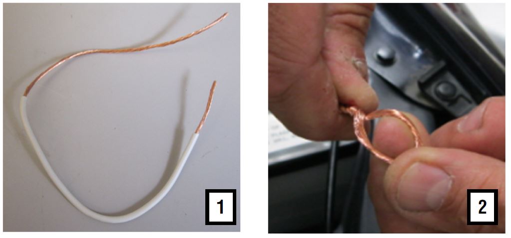
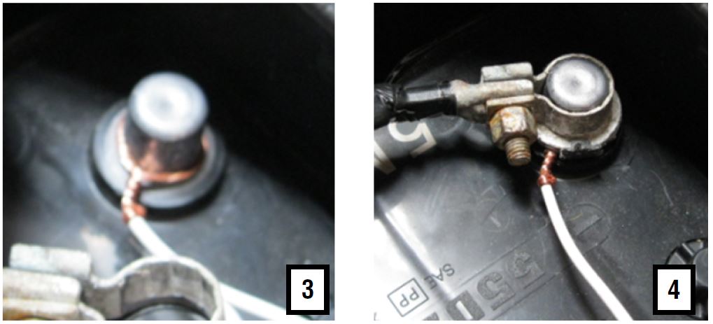
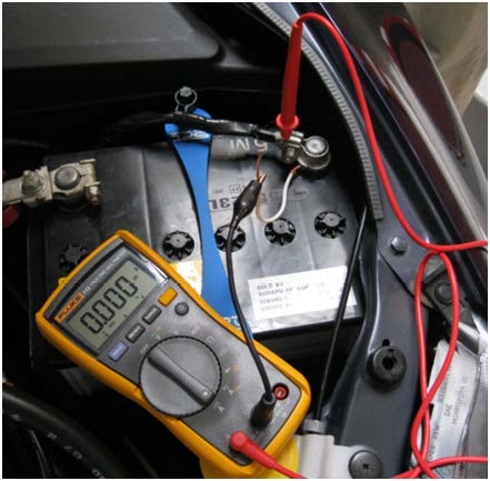
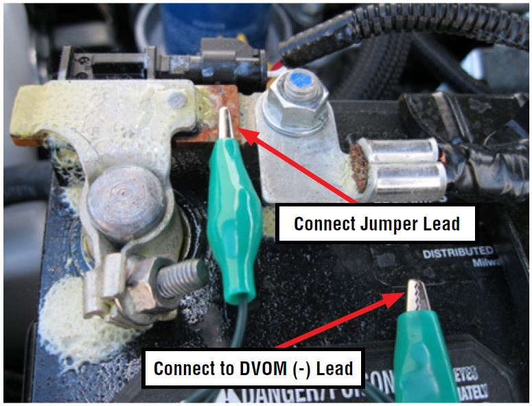
- Using a short piece of wire, make a jumper lead to connect to the negative battery post as shown in the photo sequence below. Once in place and twisted tightly around the battery post, reconnect the negative battery cable. (16 ga. wire was used for this bulletin.)
- Leaving the hood open, start the engine then position all the electrical switches as specified in the chart below.
| Electrical System | Control Switch Position |
| Headlights | ON or AUTO |
| Fog lights (if equipped) | ON |
| Wipers (Front and Rear) | On or Low Speed |
| Audio and Navigation system (OEM) | ON |
| Rear window defogger | ON |
| Dome light | Door |
| Cargo area light | Door |
| Map light | OFF |
| Air conditioner (Auto models) | ON (AUTO) |
| Air conditioner (Manual models) | ON (Speed 1) |
| EPB (Electric Parking Brake) | ON |
| All other electric components (except those items specified above). | OFF |
- After all the switches have been set according to the chart, shut off the engine and remove the ignition key.
- Leaving the hood open, exit the vehicle, making sure all the doors (including the rear gate if equipped) are fully closed. Lock all the doors and confirm all interior lights go off.
- On push-start vehicles, the smart key (remote) will need to be at least 10 feet away to allow the system to “go to sleep”. The smart key must remain away from the vehicle until testing has been completed.
- From this point, allow 5 minutes for the electrical system to stabilize (“go to sleep”) before proceeding with the actual dark current testing.
IMPORTANT:
The “window” for performing this test is only 20 minutes from the time the vehicle goes to sleep. After approximately 20 minutes, the ELCM (if equipped) testing begins and will have an effect on your test results. Another option is to wait approximately 5 hours after vehicle shut-down to perform the test. This will allow plenty of time for ELCM testing to complete and eliminates the 20-minute “window”.
- Test Procedure
- Loosen the nut securing (but do not remove) the negative (-) battery cable to the battery post.
- Connect the positive (+) probe of your ammeter to the negative (-) battery cable terminal end.
- Connect the negative (-) probe of the ammeter to the exposed end of the jumper wire.
On vehicles with a battery sensor on the negative battery terminal, leave the terminal connected and connect a jumper lead to the bus bar area between the terminal end and the 12mm nut as shown below for the feed to the DVOM. Once the DVOM is connected, remove the 12mm nut, the battery cable from the stud then perform the test. After testing, re-torque the nut to 7.5 Nm (5.5 ft. lbs.).
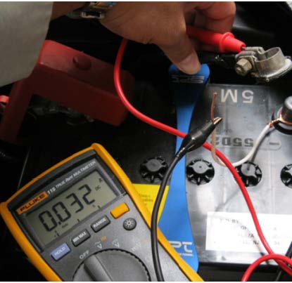
Make sure your ammeter is set to read Amperage and not Voltage. (The red lead had to be moved from the Voltage and Ohm socket to the “A” socket on the meter used in the photos.)
- While keeping the ammeter probe in contact with the negative (-) battery cable terminal and the end of the jumper wire, remove the battery cable terminal end from the battery post.
- After the current reading stabilizes, read the value displayed on the ammeter. (On push-start models, if the current reading on the ammeter continues to fluctuate, the smart key may be too close to the vehicle which will prevent the vehicle from going to sleep.)
- The Dark Current reading shown here is .032 A or 32 mA.
The maximum allowable average dark current draw is 70mA.* If the measured dark current draw exceeds 70mA, begin diagnostics by removing fuses to isolate circuits one at a time while closely monitoring the ammeter reading for a corresponding decrease. Once a circuit (or circuits) has been identified, continue with normal electrical diagnostics of that circuit to determine the source of the current draw.
* While 70mA is the maximum allowable average dark current draw, this does not mean a vehicle exhibiting an unusual current draw will always exceed 70mA. In some cases, a vehicle with less than a 70mA draw may be experiencing an unusual current draw. It is recommended whenever possible, a like comparison vehicle be used to benchmark the vehicle which has a reported unusual current draw.
- When repairs are complete, always be sure to reset the customer’s radio station presets and (if equipped) navigation system favorites before releasing the vehicle.
1 Affected Product
Vehicle
1 Associated Document
Manufacturer Communications
NUMBER: 07-85-14
DATE: 06/09/14
MC-10234831-9999.pdf 1545.597KB
 Loading...
NHTSA ID Number: 10068295
Manufacturer Communication Number: 07-85-14
Summary
MEASUREMENT OF DARK CURRENT (PARASITIC BATTERY DRAW)
1 Associated Document
Service Bulletin Document
NUMBER: 07-85-14
DATE: 06/09/14
SB-10068295-0699.pdf 1545.597KB
 Loading...
- VERSATILE FUNCTIONALITY: Measures AC/DC voltage up to 600V, 10A DC current, 2MΩ resistance; additional features include continuity, diode test and battery test
- LEAD-ALERT PROTECTION: LEDs on the meter illuminate to indicate proper test lead placement, enhancing accuracy and safety during measurements
- BACKLIT DISPLAY: LCD shows clear readings in low-light conditions for enhanced visibility
- BATTERY TEST: Battery test mode can be used for checking if batteries are working
- CONVENIENT FEATURES: Test lead holders on the back of the meter, kickstand and optional magnetic hanger (Cat. Nos. 69445 or 69417) for hands-free operation
- 【More Versatile than Expected】MS8233D multimeter can accurately measure DC/AC voltage, DC/AC current, resistance, capacitance, frequency, and duty cycle, test continuity and diode, and detect live wire and NCV.
- 【User and Device Protection】The digital multimeter conforms to IEC61010-1 CAT III 600V safety standard. Two built-in fuses provide overload protection on all ranges. Insulated rubber holster prevents the user from electric shock.
- 【6000-Count LCD Screen】Equipped with a 6000-count (3 5/6 digits) LCD display, the multimeter tester gives clear and accurate readings. Bright backlight allows for working in the dark places.
- 【More Powerful Features】The multi tester features practical functions, such as switchable manual/auto range modes, max/min value, data hold, low battery indicator, and auto power off. The multimeter has a sampling speed of 3 times per second.
- 【Non-Contact Voltage Detector】Non-contact voltage testing has sound and light alarms. When AC voltage is detected, the buzzer beeps and light flashes. The stronger the AC voltage is detected, the faster the buzzer beeps.
- Additional Tips - The following incorrect operations may cause the multimeter not to show results: Firstly, the plugs of test leads are not fully inserted or not inserted into the correct sockets. Secondly, the manual rotary switch is not placed in the correct position. In addition, this meter can not test all AC Current and below 100mV AC Voltage. Please check the user manual carefully before measurement.
- Versatile Digital Multimeter - Accurately measures AC/DC Voltage, DC Current, Resistance, and Diode. This Multimeter is a really useful tool for solving industrial and household electrical issues. Suitable for Household Outlets, Fuses, Batteries (including Vehicles), Automotive Circuit Troubleshooting, Charging Systems, Testing electronics in Cars etc.
- Troubleshooting with Accuracy - This Multimeter has a sampling speed of 2 times per second; Built-in a backlight LCD display with 3 ½ digits (1999 count) 0.6”, and high polarity including negative and positive readings.
- Ensures Safety - Double fuse is anti-burn and protects from overloading. The silicone cover can protect the multimeter from failing damage and prevent electric shocks. And low battery indication will be displayed when battery power is low.
- Ease of Use - Support Data Hold, Auto Shutoff and Continuity Buzzer. Includes Convenient feature like LCD Backlit Screen makes it easy to use in dimly light areas. Batteries/Set of Test Leads/User Manual are Included.
- Versatile Digital Multimeter - Accurately measures AC/DC Current, AC/DC Voltage, Capacitance, Frequency, Duty Cycle, Resistance, Diode, Continuity and Temperature.
- Thoughtful Design - Support Data Hold, Large LCD Backlit Screen, Auto Shut-off and Kickstand make the process of measurements easier. Professional level is reflected in some features include Auto-Ranging capability, and True RMS for measuring both AC Current and Voltage.
- Suitable For Many Occasions - This Multimeter is a golden partner to help to troubleshoot a variety of automotive and household electrical problems safely and accurately.
- Ensure Safety - Double ceramic fuse is anti-burn and protects from overloading, and it will be more secure and reliable; F400mA/600V and F10A/600V explosion-proof ceramic fuse tubes can protect the multimeter effectively.
- Additional Tips - Please take off the cap before using the test leads. Check the manual for more usage information.
- CAT III 600V Safety Rating: Ensuring your safety when working on electrical systems in common residential and commercial settings
- AC/DC Voltage Measurement up to 1000V: Quickly and accurately measure both AC and DC voltage in a wide range of applications, from automotive systems to electrical panels to commercial equipment.
- AC/DC Current Measurement up to 10A: Accurately measure AC and DC current for diagnosing electrical problems such as overloading, short circuits, and faulty wiring.
- Voltage, Resistance, Continuity, Capacitance: Essential measurement functions for troubleshooting electrical issues in a wide range of systems, allowing you to quickly diagnose and repair problems.
- Input Terminal for AC/DC Current Measurements to 10A: Allowing you to get accurate readings for a variety of electrical applications.
- ACCURATE MEASUREMENTS - The AstroAI DM200M multimeter is designed to accurately test AC/DC Voltage, AC/DC Current, Resistance, Continuity, and Diodes. These accurate readings easily and efficiently diagnose electrical issues.
- EASY TO USE - The DM200M Multimeter features data hold, max value recording, 15-minute auto power off, and a low battery indicator. It includes a silicone protective case and a kickstand for convenient use. The backlit display ensure easy troubleshooting even in dimly lit areas.
- ENHANCED SAFETY - There are two ceramic fuses that protect the multimeter from burning and overloading. The F250mA/250V and F10A/250V explosive-proof ceramic fuse tubes effectively protect the multimeter. The multimeter itself exceeds CAT III 600V safety standards.
- PORTABLE & COMPACT - This pocket-sized multimeter can easily fit in your toolbox, and you can even place it in the gloove box. It is ideal for everything from on-the-go measurements to multi-day jobs.
- WIDE APPLICATION - The AstroAI DM200M Multimeter is a versatile tool for home troubleshooting, automotive diagnostics, electrical service, electrical engineering studies, and more.
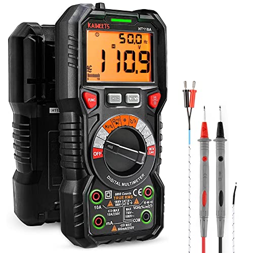
- WIDE APPLICATIONS: KAIWEETS HT118A Multimeter measures up to 1000V DC voltage and 750V AC voltage, 10A AC/DC current and 60 MOhms resistance, electrical tester also tests temperature, capacitance, frequency, duty-cycle, wire on-off, and test diodes and continuity
- EASY OPERATION: Switch the dial to the function you need, and the LED lights on the jacks will shine accordingly. To plug in the leads is easy. Autoranging saves you the hassle of having to know which range of value. Large 2.9” LCD backlight display, easy-to-read digits offer a 6000-count resolution
- MULTI-FUNCTION: Non-contact voltage testing and Live function with sound and light alarm. Flashlight on the back ensures easy use in dimly lit places. Min/Max/Average to record signal fluctuations. Stable kickstand, Pen slot on the back, Low battery prompt, Data retention, Auto power-off
- SAFETY FIRST: IEC Rated CAT III 1000V, CAT IV 600V, CE, RoHS certified. Anti-Burn with double ceramic fuse and thermistor protection circuit. High Voltage Protection is active on all ranges. Double insulated unit. Silicone protective case prevents it from falling damage
- AFTERSALES: KAIWEETS provides a 36-Month after-sale service, lifetime technical support. Please feel free to contact us if you have any concerns. Package includes multimeter, test leads, thermocouple, batteries and user manual. ( Note: Please take off the cap before using the leads)
- CAT III 600V Safety Rating: Ensuring your safety when working on electrical systems in common residential, commercial, and industrial settings.
- AC/DC Voltage and Current Measurements up to 1000V and 10A: Allowing you to get accurate readings for a variety of electrical applications.
- Resistance, Continuity, Capacitance: Essential measurement functions for troubleshooting electrical issues in a wide range of systems, allowing you to quickly diagnose and repair problems.
- Diode Test: Allows you to quickly and accurately identify faulty diodes, saving you time and money on repairs.
- Temperature measurement: Provides easy monitoring of heating and cooling systems up to 400C with included type K thermocouple.
- Smart Digital Multimeter: Thanks to its Smart Auto Mode, TESMEN TM-510 4000 counts smart digital multimeter allows you to quickly switch between all measurement tasks, including AC/DC voltage, resistance, and continuity, without selecting a mode or range. It makes measuring work easy, fast, and accurate
- Non-contact: Completely safe Non-Contact Voltage test with a visual and audible alarm; a time-saving and safe feature. You can measure the voltage on the AC wire without having to connect the wire, which makes troubleshooting the line much easier
- Safety Guarantee: CAT II 600V, CE, and RoHS certified. Overload protection measures are used inside the instrument to improve the product's safety performance and maximise users' safety. The outer silicone cover protects the multimeter from damage and potential electric shock
- User Friendly: Supports Data Hold, Automatic Shutdown, Low battery indicator, Backlight display, and Flashlight. All these convenience features make the instrument more than enough for daily use by amateurs, car owners, and homeowners. Easy to use, enjoy endless DIY fun
- What you will get: Package includes a digital multimeter, 2 test leads, a storage bag, 2 AAA batteries, and a user manual
- 【Recording Mode】FNIRSI multimeter can plot measured value ripple that changes over time is drawn, and the fluctuation of voltage or current over time can be observed. 8 measured values can be recorded, and the Max and Min measurement values are displayed
- 【Monitoring mode】Custom thresholds can be set in multimeter monitoring mode, and a warning will be issued if the voltage exceeds or falls below the set threshold
- 【Solving hunger】Built-in 1500 mAh rechargeable battery allows the multimeter tester to work longer. No more manually replacing bulky, unfindable disposable batteries, the Type-c port renews energy at any time
- 【Intelligent Mode】In intelligent mode, DMT-99 digital multimeter can identify the measurement content and select the range with the best resolution, making the measurement more convenient and faster,Takes out the guesswork for most applications
- 【Private customization】2.4-inch full-color TFT screen display, 240*320 resolution, makes it easy to use in dimly light areas. Supports DIY startup interface and creates your own personal entry interface
SEOCONTENT-START
Service Information Number: 07-85-14; Date: 06/09/14 Page 1
INTRODUCTION
This bulletin will provide the proper procedure for measuring Dark Current (parasitic battery draw)
along with the specification for maximum allowable limits. Customer concerns of batteries going
dead over a period of time should be diagnosed using this procedure once any obvious contributing
factors have been eliminated.
SERVICE PROCEDURE / INFORMATION
1- Vehicle Preparation
• Before beginning this procedure, the vehicle’s battery must be fully charged and in peak
operating condition. If needed, charge the battery fully using the MidTronics GR8 or replace
it if your diagnosis determines necessary. A battery in poor condition or in need of charge
will likely have an adverse effect on the accuracy of the dark current draw test results.
• The battery posts and cable ends must be free of corrosion, dirt, sealer and in good condition.
• Be sure to record the customer’s radio station pre-sets and navigation system favorites (if
applicable) as they will be lost during the test along with any seat memory settings. DO
NOT use an aftermarket 9-volt memory retention device in the power outlet to retain any
ECU memory.
• Disconnect or remove any aftermarket (non-OEM) electrical accessories or equipment.
• Install the back-up power supply fuse then, (if applicable) using the SSMIII, confirm the
Body Integrated Unit (BIU) is set “Market Mode”.
• Using a short piece of wire, make a jumper lead to connect to the negative battery post as
shown in the photo sequence below. Once in place and twisted tightly around the battery
post, reconnect the negative battery cable. (16 ga. wire was used for this bulletin.)
NUMBER: 07-85-14
DATE: 06/09/14
APPLICABILITY: All Models
SUBJECT: Measurement of “Dark Current”
(Parasitic Battery Draw)
SERVICE INFORMATION
ATTENTION:
GENERAL MANAGER q
PARTS MANAGER q
CLAIMS PERSONNEL q
SERVICE MANAGER q
IMPORTANT – All
Service Personnel
Should Read and
Initial in the boxes
provided, right.
Continued…
CAUTION: VEHICLE SERVICING PERFORMED BY UNTRAINED PERSONS COULD
RESULT IN SERIOUS INJURY TO THOSE PERSONS OR TO OTHERS.
Subaru Service Bulletins are intended for use by professional technicians ONLY. They
are written to inform those technicians of conditions that may occur in some vehicles,
or to provide information that could assist in the proper servicing of the vehicle. Properly
trained technicians have the equipment, tools, safety instructions, and know-how to
do the job correctly and safely. If a condition is described, DO NOT assume that this
Service Bulletin applies to your vehicle, or that your vehicle will have that condition.
SUBARU OF AMERICA, INC. IS
ISO 14001 COMPLIANT
ISO 14001 is the international standard for
excellence in Environmental Management
Systems. Please recycle or dispose of
automotive products in a manner that is friendly
to our environment and in accordance with all
local, state and federal laws and regulations.
©2014 Subaru of America, Inc. All rights reserved.
1 2
Service Information Number: 07-85-14; Date: 06/09/14 Page 2
• Leaving the hood open, start the engine then position all the electrical switches as specified in
the chart below.
Electrical System Control Switch Position
Headlights ON or AUTO
Fog lights (if equipped) ON
Wipers (Front and Rear) On or Low Speed
Audio and Navigation system (OEM) ON
Rear window defogger ON
Dome light Door
Cargo area light Door
Map light OFF
Air conditioner (Auto models) ON (AUTO)
Air conditioner (Manual models) ON (Speed 1)
EPB (Electric Parking Brake) ON
All other electric components
(except those items specified above). OFF
• After all the switches have been set according to the chart, shut off the engine and remove the
ignition key.
• Leaving the hood open, exit the vehicle, making sure all the doors (including the rear gate if
equipped) are fully closed. Lock all the doors and confirm all interior lights go off.
• On push-start vehicles, the smart key (remote) will need to be at least 10 feet away to allow
the system to “go to sleep”. The smart key must remain away from the vehicle until
testing has been completed.
• From this point, allow 5 minutes for the electrical system to stabilize (“go to sleep”) before
proceeding with the actual dark current testing.
IMPORTANT:
The “window” for performing this test is only 20 minutes from the time the vehicle goes to sleep.
After approximately 20 minutes, the ELCM (if equipped) testing begins and will have an effect on
your test results. Another option is to wait approximately 5 hours after vehicle shut-down to perform
the test. This will allow plenty of time for ELCM testing to complete and eliminates the 20-minute
“window”.
3 4
Continued…
Service Information Number: 07-85-14; Date: 06/09/14 Page 3
2- Test Procedure
• Loosen the nut securing (but do not remove) the negative (-) battery cable to the battery post.
• Connect the positive (+) probe of your ammeter to the negative (-) battery cable terminal end.
• Connect the negative (-) probe of the ammeter to the exposed end of the jumper wire.
On vehicles with a battery sensor on the negative battery terminal, leave the terminal connected
and connect a jumper lead to the bus bar area between the terminal end and the 12mm nut as shown
below for the feed to the DVOM. Once the DVOM is connected, remove the 12mm nut, the battery
cable from the stud then perform the test. After testing, re-torque the nut to 7.5 Nm (5.5 ft. lbs.).
Connect Jumper Lead
Connect to DVOM (-) Lead
Continued…
Service Information Number: 07-85-14; Date: 06/09/14 Page 4
Make sure your ammeter is set to read Amperage and not Voltage. (The red lead had to be moved
from the Voltage and Ohm socket to the “A” socket on the meter used in the photos.)
• While keeping the ammeter probe in contact with the negative (-) battery cable terminal and
the end of the jumper wire, remove the battery cable terminal end from the battery post.
• After the current reading stabilizes, read the value displayed on the ammeter. (On push-start
models, if the current reading on the ammeter continues to fluctuate, the smart key may be
too close to the vehicle which will prevent the vehicle from going to sleep.)
• The Dark Current reading shown here is .032 A or 32 mA.
The maximum allowable average dark current draw is 70mA.* If the measured dark current draw
exceeds 70mA, begin diagnostics by removing fuses to isolate circuits one at a time while closely
monitoring the ammeter reading for a corresponding decrease. Once a circuit (or circuits) has been
identified, continue with normal electrical diagnostics of that circuit to determine the source of the
current draw.
* While 70mA is the maximum allowable average dark current draw, this does not mean a vehicle
exhibiting an unusual current draw will always exceed 70mA. In some cases, a vehicle with less
than a 70mA draw may be experiencing an unusual current draw. It is recommended whenever
possible, a like comparison vehicle be used to benchmark the vehicle which has a reported unusual
current draw.
• When repairs are complete, always be sure to reset the customer’s radio station presets and
(if equipped) navigation system favorites before releasing the vehicle.
**************************************************************************************************************
**************************************************************************************************************
SEOCONTENT-END
Last update on 2025-05-08 / Affiliate links / Images from Amazon Product Advertising API
This product presentation was made with AAWP plugin.

