| “This site contains affiliate links for which OEMDTC may be compensated” |
NHTSA ID Number: 10182592
Manufacturer Communication Number: 078915R
Summary
NOTE: As of 8/23/2016, this TSB has been replaced with Service Program Bulletins WTG-67 and WTH-68. Please refer to those publications for the most updated information relating to the repairs originally contained in TSB 07-89-15R.
NUMBER: 07-89-15R
DATE: 02-10-15
REVISED: 08-23-16
NOTE: As of 8/23/2016, this TSB has been replaced with Service Program Bulletins WTG-67 and WTH-68. Please refer to those publications for the most updated information relating to the repairs originally contained in TSB 07-89-15R.
NUMBER: 07-89-15R
DATE: 02-10-15
REVISED: 01-04-16
| APPLICABILITY: | 2015-16MY Legacy and Outback Models |
| SUBJECT: | Interior Fuse Box (F/B) “IG” and “ACC” Relay Under-Hood Fuse Box (M/B) Main Relay Replacement for Engine Will Not Crank / Start Condition |
INTRODUCTION
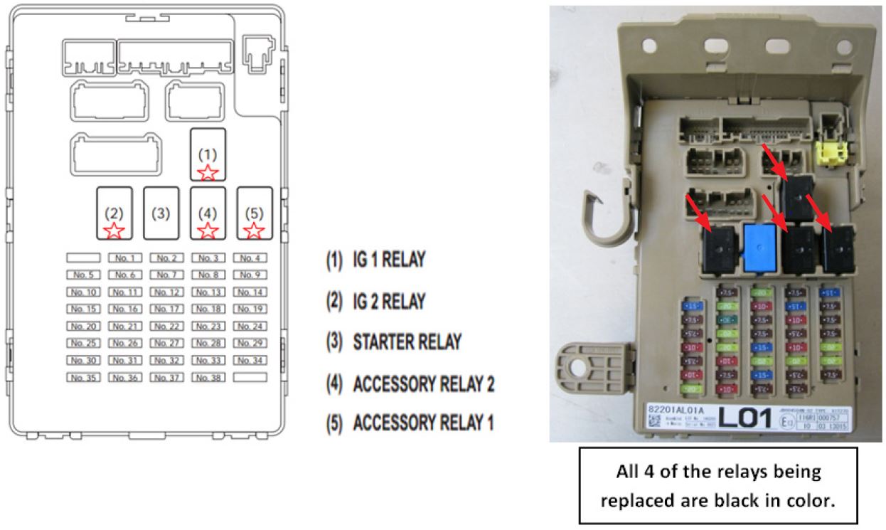
If you receive a customer concern of a no crank / no start condition during very cold temperatures, the IG1, IG2, ACC1, ACC2 and/or the EGI Main relays may be the root cause and require replacement. It is generally reported that the car starts normally after an overnight soak. After the initial start, the customer drives a short distance then shuts the car off (example: at a gas pump or coffee shop). After the time that it takes to pump their gas or get their coffee, they return to the car and it will not start. The customer may also notice the instrument cluster and/or interior lights are not illuminating along with the HVAC being inoperative. The source of this condition has been identified as condensation flash-freezing inside the relays. This bulletin provides a service procedure for replacement of all 5 relays, 4 of which are located together in the vehicle’s interior fuse box (F/B) and the EGI Main relay which is located in the under-hood Main fuse box (M/B).
PRODUCTION CHANGE INFORMATION
The new IG1, IG2, ACC1, and ACC2 relays were incorporated into production starting with the following VINs:
Legacy: F*048310
Outback: F*296775
The new EGI Main Relays were incorporated into production October 5, 2015 starting with the following VINs:
Legacy: G*017247
Outback: G*237505
PART INFORMATION
The new relay part numbers are: 82501AL000 (qty. 4, IG1, IG2, ACC1, ACC2 RELAY ASSEMBLY) 25232AA130
 (qty. 1, EGI-MAIN RELAY)
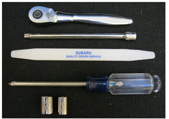
TOOLS REQUIRED
- 1/4” Drive Ratchet
- 6” 1/4” Drive Extension
- Plastic Trim Tool
- #2 Phillips Screw Driver
- 10mm and 12mm sockets
SERVICE PROCEDURE
*VERY IMPORTANT: To prevent damage to the F/B itself or the relay connections inside it, the F/B MUST be removed from the vehicle and allowed to stabilize to a reasonable temperature PRIOR to relay removal. DO NOT attempt to remove the relays with the F/B still installed in the vehicle.
- Remove the 12mm nut and disconnect the negative cable from the battery temperature sensor.
- Release the 3 push clips securing the under dash cover and push it up towards the pedals / bulkhead to get it out of the way.
- Using a plastic trim tool, CAREFULLY remove the trim cover on the end of the instrument panel. Once removed, you will have access to the 1 Philips screw at the bottom, just above the hood release lever which secures the lower dash trim panel.
- The remaining fasteners securing the lower dash trim panel are simply claws which will release easily. Once the trim panel is removed, unplug the harness connectors and put the panel aside.
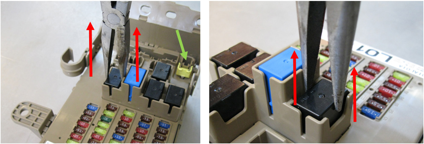
- There are three – 10mm hex fasteners securing the F/B to the dash structure; a bolt at the bottom and 2 nuts at the top on studs. Remove the 3 fasteners and start CAREFULLY unplugging harness connectors as you drop the F/B down, gaining more access as each harness connector is released. There are 16 harness connectors plugged into the F/B. Use a plastic trim tool to release the hinged yellow cover for the connector in the upper right corner (green arrow in photo below).
*IMPORTANT REMINDER: To prevent damage to the F/B itself or relay connections inside it, the F/B MUST be removed from the vehicle and allowed to stabilize to reasonable temperature PRIOR to relay removal. DO NOT attempt to remove the relays with the F/B still installed in the vehicle.
- Using a large pair of needle-nosed pliers, remove the 4 black relays by PULLING STRAIGHT UP on them in a motion perpendicular to the F/B as shown in the photos below. DO NOT WIGGLE THEM as damage to the relay connectors or the F/B itself may result.
- Once ALL 4 of the black relays have been replaced, reinstall the F/B and re-assemble in the opposite order of removal.
NOTE: Always make sure all of the harness connectors are fully locked back in place (audible “click”) as each one is plugged back into the F/B.
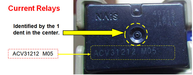
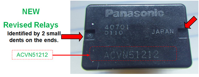
IMPORTANT: Relay identification:
The photos above show the IG1, IG2, ACC1 and ACC2 relays. The EGI Main Relay photos are shown below.
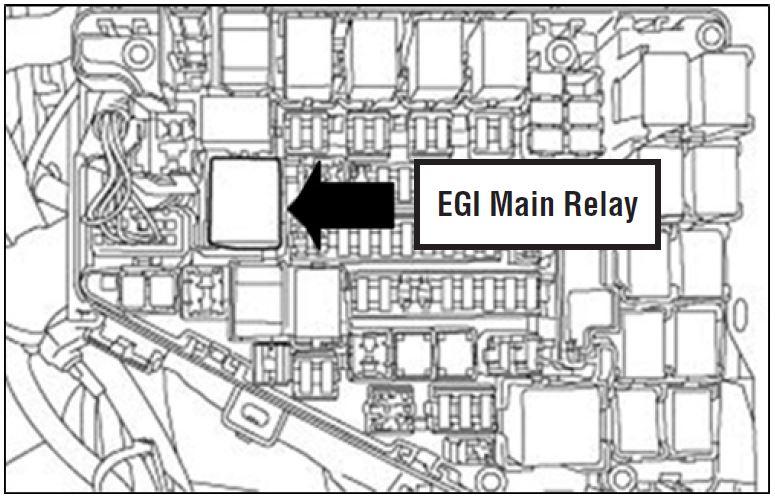
- Remove the under-hood M/B cover and CAREFULLY replace the EGI Main Relay indicated in the illustration below.
Under-hood Main Fuse Box (M/B)
NOTE: Make sure all of the harness connectors are fully locked back in place (audible “click”) as each one is plugged back into the F/B.
- Reconnect the battery cable and torque the 12mm nut to 5.5 ft. lbs.
- Start the car and verify all the combination meter warning lights cycle on / off normally.
- For the power window Auto Up / Down feature to operate, the system will need to be re-initialized on BOTH front doors.
- Confirm the HVAC and all electrical systems operate as designed to complete the repair.
4 Affected Products
Vehicles
1 Associated Document
Manufacturer Communications
NUMBER: 07-89-15R
DATE: 02-10-15
REVISED: 08-23-16
MC-10182592-9999.pdf 155.015KB
 Loading...
NHTSA ID Number: 10074609
Manufacturer Communication Number: 07-89-15R
Summary
SUMMARY TO BE PROVIDED ON A FUTURE DATE.
1 Associated Document
Service Bulletin Document
NUMBER: 07-89-15R
DATE: 02-10-15
REVISED: 01-04-16
SB-10074609-2280.pdf 841.171KB
 Loading...
| “This site contains affiliate links for which OEMDTC may be compensated” |
- High switching capability: Normally open 40A/14V DC and normally close 30A/14V DC. Suitable for Nilight LED light bar wiring harness kit
- Premium quality: Durable relay and harness socket with 5 wires; Made by high-grade materials to ensure superior quality and long lifespan
- Male-female slot design: Unique male-female slot design, easy to connect the relay with harness socket, clean and neat after installation
- Easy wiring: The relay sockets come with different colors for loads/accessories, simple and convenient wiring
- Package include: 5 x relay and 5 x relay socket with wires.Fit type: Universal fit
- Never go beyond its capabilities. Try to stay 10 to 15% below what the rate is for
- 12-volt 5-prong relay. Excellent water-repellent and dustproof ability, but not using it in water
- Be careful when inserting the relay into the socket. If you force it, you will bend the female connectors
- Primary leads use 12 a.w.g tinned copper wire. Coil leads use 16 a.w.g
- Nominal Coil Voltage: 12 V DC; Coil Power: 1.8 W; Coil Resistance: 80 Ω; Must Operate Voltage: 6~8 V DC; Must Release Voltage: 0.6~3.6 V DC; Maximum Applied Voltage: 15.6 V DC
- Brand new heavy duty SPST(Single Pole Single Throw) relays with color-labeled wires.
- Minimum operating voltage 8V, corresponding minimum operating current is 100mA; Standard operating voltage 12V, corresponding standard operating current is 150mA.
- Small size/Low power consumption/High contact voltage/ High sensitivity.
- Contact Material: Ag Alloy / Contact Resistance: ≤ 100MΩ.
- Life Expectancy Electrical: 100,000 Operation, Life Expectancy Mechanical: 10,000,000 Operation.
- Easy Wiring - The relay sockets come with color-labeled wires for loads/accessories convenient wiring. Black - Ground (85), Red - VDC (30), White - Trigger (86), Blue - Output N/O (87).
- Neat Mounting Design - The interlocking design of unique male-female slot on each socket edge, easy to connect all relays together, offering clean and neat installation.
- Upgraded Version - Automotive relays built in fuse socket with included 30A blade fuse, no need of a separate fuse holder, saving space and money. Heavy duty 12AWG wires for main contact.
- Good Construction - 12V DC (Max14V DC) and 30A High Switching Capability. Bosch style 4-Pin SPST (Single Pole Single Throw) Relay. Metal mounting bracket on the electrical relay promotes easy installation.
- Wide Application - Wide range of use, greatly used for car lights, fog lamps, wiper, starter, fans, speakers, traction control systems, etc.
- 12 V DC automotive waterproof relays (max 14 V). Note: 12 V and 14 V are coil voltages, they are not the voltage that triggers the switch
- Premium quality: durable relay and harness socket with 5 wires; made from high-grade materials to ensure superior quality and long lifespan
- Pre-wired Harness: Heavy duty 12/16 AWG wiring harness. Black - 16AWG Pin85, White - 16AWG Pin86, Red - 12AWG Pin30 Yellow - 12AWG Pin87a, and Blue - 12AWG Pin87
- Enhanced Waterproof - The 5-Pin relays are tightly sealed with strong cap and seal ring, excellent performance of waterproof, dust proof and moisture proof, works well in any weather conditions
- Package includes: 5 pack Waterproof Relay and Harness. 1x User manual
- 12V Relay Module: Working Voltage: DC 12V; Maximum Load: AC 250V/10A, DC 30V/10A; Trigger Current of Opto-Isolator: 5mA
- Fault-Tolerant Design: Fault Tolerant Design, Even if the Control Line is Broken, the Relay will not Operate;All Interfaces of Relay can be Wired Out Through the Terminals Directly,Normally Open and Normally Closed
- Optocoupler Isolation:1 Channel Relay Board use Optocoupler Isolation that has Strong Driving Ability and Stable Performance ,The Isolation Circuit Prevent Damages to I / O Port by Relay Switch Current
- Jumper Design: The Relay Module has a Jumper That You Can Set Rather the Unit State Changes with High or Low Signal. Has Screw Terminals for Relay (NC,C,NO) and for Input; Coil +, Coil - and Trigger.
- Wide Application: DC 12V Relay Module Works Well with ARM /PIC /AVR /MCU/Raspberry/CNC Machine/ PS4 etc.
- 5 Pin SPDT (Single Pole Double Throw) Bosch Style Electrical Relay.
- 40A/30A High Switching Capability. These relays have a universal application and can be used in a 12 Volt DC power source, such as automotive setups, car sound systems, security systems, and various other applications.
- Pin Specifications: 30V DC. Ground (85), Trigger (86), Output N/C (87a), and Output N/O (87).
- Maximum Applied Voltage: 15.6 V DC; Max Operating Voltage is 27V DC; Nominal Coil Voltage: 12 V DC; Max Operating Current: 40A; Must Operate Voltage: 6~8 V DC; Must Release Voltage: 0.6~3.6 V DC; Coil Power: 1.8 W; Coil Resistance: 80 Ω; Insulation Resistance: 100MΩ
- Package include: 10 pack electrical relays. Sockets are not included
- Never go beyond its capabilities. Try to stay 10 to 15% below what the rate is for
- 12-volt 4-prong relay. Excellent water-repellent and dustproof ability, but not using it in water
- For the people whose relays are burning, please make sure you are making tight connections (especially on the load wires), read the specs on the item description, and ensure that the operating environment meets the safety requirements of the relay
- Be careful when inserting the relay into the socket. If you force it, you will bend the female connectors
- Thick 12 gauge wire for the load terminals. Easy to install just make sure you follow the wiring diagram. Works for both positive and negative activation
- [BOSCH EXPERTISE] - Bosch has been producing relays for vehicles and other applications for more than 40 years - this vast development experience ensures continuous advancement in design features to deliver optimum performance
- [COMPACT SWITCHING] - Bosch Mini Relays feature a compact design and are used in a wide range of vehicles to perform switching operations
- [PREMIUM PERFORMANCE] - Bosch relays incorporate only the highest quality materials for reliable, long-term performance and a 250,000 switching cycle capability
- [SUPERIOR ENGINEERING] - Engineered with high corrosion resistance to ensure long term reliability in harsh environments and conditions
- 5 pins, 12V, 30A; Integral bracket mount; Black Note: Both 87 pins (no 87a) are permanently connected. Relay should be wired like a 4 pin. Not for use where a true 5 pin relay is required
- 4 Pin SPST Harness Sockets with Color-labeled Wires : Rated Operational Voltage:12V; Switching Capability: 40A
- Standard Operating Voltage 8V; Corresponding Standard Operating Current: 100mA; Minimum Operating Voltage 12V; Corresponding Minimum Operating Current: 150mA
- High Quality: Car Relay with Harness 4 Pin SPDT Harness Sockets Made of High-Grade Materials to Ensure Superior Quality and Long Lifespan,Small Size, Low Power Consumption, High Contact Voltage, High Sensitivity
- Male-Female Slot Design: Auto Relay Designed with Unique Male-Female Slot, Plug and Play ,Easy to Connect the Relay with Harness Socket, Clean and Neat after Installation
- Easy Wiring: Car Relay Sockets Come with Different Colors Wires for Loads/Accessories,Heavy Duty SPDT (Single Pole Double Throw) Relays with Color-Labeled Wires. Simple and Convenient Wiring.Suitable for Automotive Truck Van Motorcycle Boat
Last update on 2025-05-08 / Affiliate links / Images from Amazon Product Advertising API
This product presentation was made with AAWP plugin.
SEOCONTENT-START
Bulletin Number: 07-89-15R Revised: 01/04/16 Page 1 INTRODUCTION If you receive a customer concern of a no crank / no start condition during very cold temperatures, the IG1, IG2, ACC1, ACC2 and/or the EGI Main relays may be the root cause and require replacement. It is generally reported that the car starts normally after an overnight soak. After the initial start, the customer drives a short distance then shuts the car off (example: at a gas pump or coffee shop). After the time that it takes to pump their gas or get their coffee, they return to the car and it will not start. The customer may also notice the instrument cluster and/or interior lights are not illuminating along with the HVAC being inoperative. The source of this condition has been identified as condensation flash-freezing inside the relays. This bulletin provides a service procedure for replacement of all 5 relays, 4 of which are located together in the vehicle’s interior fuse box (F/B) and the EGI Main relay which is located in the under-hood Main fuse box (M/B). PRODUCTION CHANGE INFORMATION The new IG1, IG2, ACC1, and ACC2 relays were incorporated into production starting with the following VINs: Legacy: F*048310 Outback: F*296775 The new EGI Main Relays were incorporated into production October 5, 2015 starting with the following VINs: Legacy: G*017247 Outback: G*237505 PART INFORMATION The new relay part numbers are: 82501AL000 (qty. 4, IG1, IG2, ACC1, ACC2 RELAY ASSEMBLY) 25232AA130 (qty. 1, EGI-MAIN RELAY) TOOLS REQUIRED NUMBER: 07-89-15R DATE: 02-10-15 REVISED: 01-04-16 APPLICABILITY: 2015-16MY Legacy and Outback Models SUBJECT: Interior Fuse Box (F/B) “IG” and “ACC” Relay Under-Hood Fuse Box (M/B) Main Relay Replacement for Engine Will Not Crank / Start Condition SERVICE INFORMATION ATTENTION: GENERAL MANAGER q PARTS MANAGER q CLAIMS PERSONNEL q SERVICE MANAGER q IMPORTANT – All Service Personnel Should Read and Initial in the boxes provided, right. ©2015 Subaru of America, Inc. All rights reserved. CAUTION: VEHICLE SERVICING PERFORMED BY UNTRAINED PERSONS COULD RESULT IN SERIOUS INJURY TO THOSE PERSONS OR TO OTHERS. Subaru Service Bulletins are intended for use by professional technicians ONLY. They are written to inform those technicians of conditions that may occur in some vehicles, or to provide information that could assist in the proper servicing of the vehicle. Properly trained technicians have the equipment, tools, safety instructions, and know-how to do the job correctly and safely. If a condition is described, DO NOT assume that this Service Bulletin applies to your vehicle, or that your vehicle will have that condition. SUBARU OF AMERICA, INC. IS ISO 14001 COMPLIANT ISO 14001 is the international standard for excellence in Environmental Management Systems. Please recycle or dispose of automotive products in a manner that is friendly to our environment and in accordance with all local, state and federal laws and regulations. Continued… • 1/4” Drive Ratchet • 6” 1/4” Drive Extension • Plastic Trim Tool • #2 Phillips Screw Driver • 10mm and 12mm sockets Bulletin Number: 07-89-15R Revised: 01/04/16 Page 2 SERVICE PROCEDURE *VERY IMPORTANT: To prevent damage to the F/B itself or the relay connections inside it, the F/B MUST be removed from the vehicle and allowed to stabilize to a reasonable temperature PRIOR to relay removal. DO NOT attempt to remove the relays with the F/B still installed in the vehicle. • Remove the 12mm nut and disconnect the negative cable from the battery temperature sensor. • Release the 3 push clips securing the under dash cover and push it up towards the pedals / bulkhead to get it out of the way. • Using a plastic trim tool, CAREFULLY remove the trim cover on the end of the instrument panel. Once removed, you will have access to the 1 Philips screw at the bottom, just above the hood release lever which secures the lower dash trim panel. • The remaining fasteners securing the lower dash trim panel are simply claws which will release easily. Once the trim panel is removed, unplug the harness connectors and put the panel aside. • There are three – 10mm hex fasteners securing the F/B to the dash structure; a bolt at the bottom and 2 nuts at the top on studs. Remove the 3 fasteners and start CAREFULLY unplugging harness connectors as you drop the F/B down, gaining more access as each harness connector is released. There are 16 harness connectors plugged into the F/B. Use a plastic trim tool to release the hinged yellow cover for the connector in the upper right corner (green arrow in photo below). Continued… Bulletin Number: 07-89-15R Revised: 01/04/16 Page 3 *IMPORTANT REMINDER: To prevent damage to the F/B itself or relay connections inside it, the F/B MUST be removed from the vehicle and allowed to stabilize to reasonable temperature PRIOR to relay removal. DO NOT attempt to remove the relays with the F/B still installed in the vehicle. • Using a large pair of needle-nosed pliers, remove the 4 black relays by PULLING STRAIGHT UP on them in a motion perpendicular to the F/B as shown in the photos below. DO NOT WIGGLE THEM as damage to the relay connectors or the F/B itself may result. • Once ALL 4 of the black relays have been replaced, reinstall the F/B and re-assemble in the opposite order of removal. NOTE: Always make sure all of the harness connectors are fully locked back in place (audible “click”) as each one is plugged back into the F/B. IMPORTANT: Relay identification: The photos above show the IG1, IG2, ACC1 and ACC2 relays. The EGI Main Relay photos are shown below. Continued… OLD: M07 NEW: M09 Bulletin Number: 07-89-15R Revised: 01/04/16 Page 4 • Remove the under-hood M/B cover and CAREFULLY replace the EGI Main Relay indicated in the illustration below. NOTE: Make sure all of the harness connectors are fully locked back in place (audible “click”) as each one is plugged back into the F/B. • Reconnect the battery cable and torque the 12mm nut to 5.5 ft. lbs. • Start the car and verify all the combination meter warning lights cycle on / off normally. • For the power window Auto Up / Down feature to operate, the system will need to be re-initialized on BOTH front doors. • Confirm the HVAC and all electrical systems operate as designed to complete the repair. WARRANTY / CLAIM INFORMATION For vehicles within the Basic New Car Limited Warranty period or covered by a Subaru Added Security Classic or Gold plan, this repair may be submitted using the following claim information: LABOR DESCRIPTION LABOR OPERATION # FAIL CODE LABOR TIME Interior Fuse Box (F/B) R&R and Relay Replacement Procedure A860-062 UQW-48 0.6 IMPORTANT REMINDERS: • SOA strongly discourages the printing and/or local storage of service information as previously released information and electronic publications may be updated at any time. • Always check for any open recalls or campaigns anytime a vehicle is in for servicing. • Always refer to STIS for the latest service information before performing any repairs. EGI Main Relay Under-hood Main Fuse Box (M/B)
**************************************************************************************************************
SEOCONTENT-END

