| “This site contains affiliate links for which OEMDTC may be compensated” |
NUMBER: 07-94-15
DATE: 07/23/15
| APPLICABILITY: | 2013MY BRZ |
| SUBJECT: | Interference between the Fender and Side Marker Lamp |
INTRODUCTION
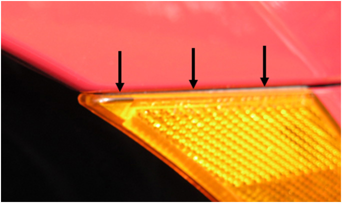
This bulletin provides a repair procedure to address concerns of contact between the top horizontal edge of the side marker lamp and the corresponding fender edge as shown in the photo to the right.
PART INFORMATION
3 pieces (maximum per lamp) 71MM (3 13/16”) long x 3mm (1/8”) wide of non-woven tape.
| PART NAME: | PART NUMBER: |
| Non-Woven Tape (8” X 11” sheet, .43mm thick) | SOA963W110 |
SERVICE PROCEDURE
CAREFULLY remove the side marker lamp (procedure copied from Service Bulletin 07-68-12).
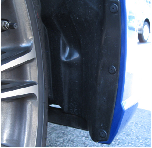
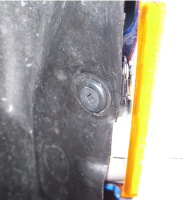
Most of the photos used in this procedure were taken with the vehicle on a lift. With the suspension relaxed, there is more room available to access the inner fender liner retaining clips. In addition, turning the wheels to the right fully will provide more access to the left (Driver’s) side inner fender area and vice-versa. Remove the 4 inner fender liner retaining clips shown in the photos below.
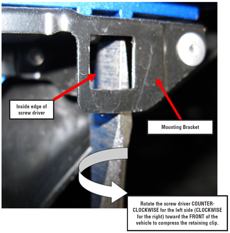
Once the 4 clips are removed, access the side marker lamp retaining bracket by moving the liner out of the way. The next photo shows the Driver’s (Left) side marker light retaining bracket with a medium-sized flat-blade screw driver inserted into the proper position prior to rotation used to compress the side marker lamp’s retaining clip (the side marker lamp was removed in the photo below for illustration purposes). To release the left-hand (Driver’s side) retaining clip, SLOWLY rotate the inside edge of the screw driver COUNTER-CLOCKWISE toward the front of the car.
If turned in the opposite direction, the retaining clip will be damaged and most likely not retain the lamp properly after re-installation. CAREFULLY turn the screw driver with one hand while pulling outward on the top of the lamp slightly with the other to help with the release from the mounting bracket. It is very important to TAKE YOUR TIME and not compress the retaining clip any further than necessary or its ability to properly retain the lamp upon reassembly may be lost.
REMINDER: The retaining clips are part of the lamp assembly and not available separately.
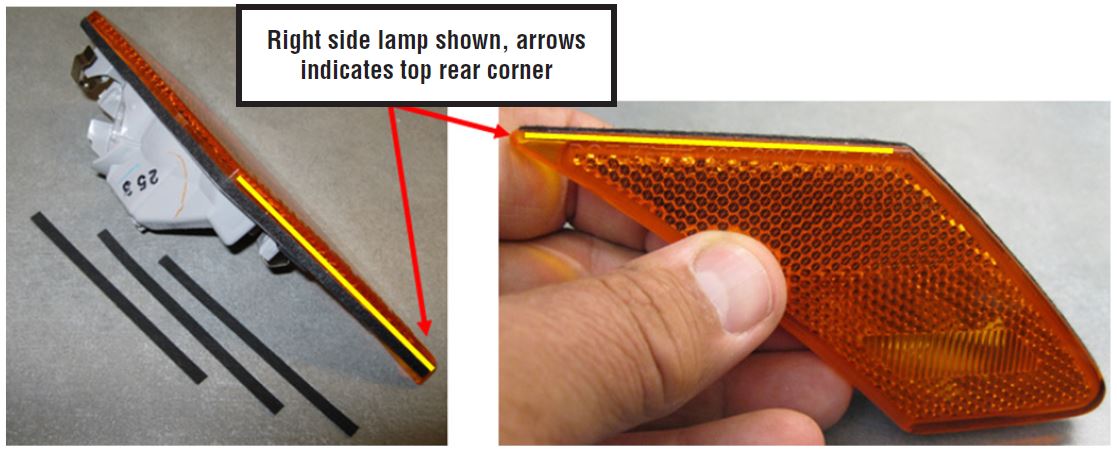
After removing the side marker lamp, lightly clean the currently installed tape in the highlighted area shown in the photos above with a mild solvent on a clean shop cloth. Dry the lamp thoroughly before applying the new tape.
Inspect the existing tape on the lamp.
- If the original tape is chaffed or otherwise damaged, remove it from the top edge along with any remaining glue residue and apply 3 layers of the new non-woven tape (see Parts Information for tape dimensions) to achieve an approximate 1.5 mm thickness.
- If the existing tape is not damaged or worn, peel the backing and apply 2 layers of nonwoven tape (see Parts Information for tape dimensions) directly over top of it to achieve an approximate 1.5mm thickness.
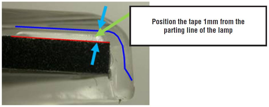
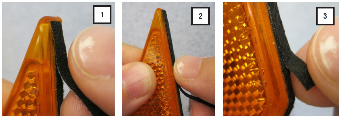
Start the first layer at the rear corner of the lamp and 1mm from the parting line as shown in the photo sequence below.
Repeat as needed to achieve the approximate 1.5mm total tape thickness required.
Reinstall the side marker lamp and reassemble in reverse order. Before re-installing the lamp assembly, always confirm the bulb operates normally. Next, confirm the retaining clips are fully inserted into their proper positions on the back of the housing and the gap measures 3mm (.118”) as shown in the below illustration (a) below. If the end gap on the clip is less than 3mm, the side marker lamp will not be secured properly in the retaining bracket and feel like it is loose. Use needle-nose pliers to adjust the end gap if necessary. If any of the retaining clips break, loose tension, get sprung up away from the lamp body or become dislodged, the lamp assembly will need to be replaced. In addition, be sure to straighten any deformation and address any scratches which may have occurred to the mounting bracket during side marker lamp removal with touch-up paint.
After the lamp is re-installed into the mounting bracket, refit the inner fender liner.
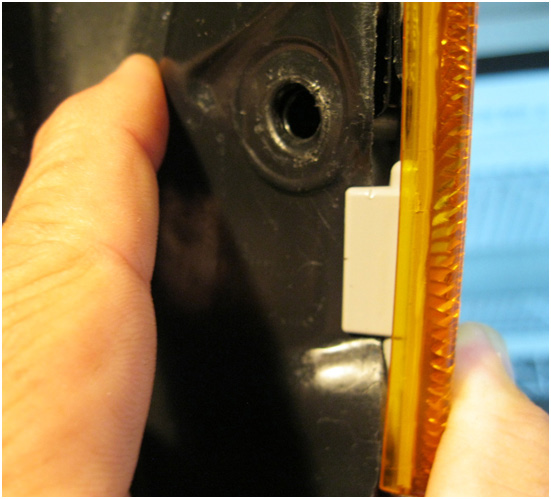
NOTE: The liner must fit behind the tab molded into the base of the marker light assembly as shown in the photo below.
To complete the procedure, confirm the liner is fully seated behind the fender lip the rest of the way around the wheel arch to keep water from getting behind it. Install the 4 liner retaining clips.
WARRANTY / CLAIM INFORMATION
For vehicles within the Basic New Car Limited Warranty period, this repair may be claimed using the following information:
| LABOR DESCRIPTION | LABOR OPERATION # | FAIL CODE | LABOR TIME |
|---|---|---|---|
| ONE FRONT SIDE MARKER LAMP INTERFERENCE
REPAIR | A916-191 | XCF-48 | 0.4 |
| BOTH FRONT SIDE MARKER LAMPS INTERFERENCE REPAIR | A916-194 | 0.6 |
REMINDER: SOA strongly discourages the printing and/or local storage of service information as previously released information and electronic publications may be updated at any time.
Always refer to STIS for the latest service information before performing any repairs.
