| “This site contains affiliate links for which OEMDTC may be compensated” |
NUMBER: 07-116-16R
DATE: 11/11/16
REVISED: 12/30/16
| APPLICABILITY: | All Affected Models |
|---|---|
| SUBJECT: | Supplemental Service Procedure Information to be Used in Conjunction with Campaigns WQP-51, WQR-53R and TKA, B, C-16R |
INTRODUCTION:
This Service Information bulletin is intended to provide helpful tips to Technicians performing the above-listed airbag inflator assembly replacement recalls. This information should increase Technician efficiency and the recall completion percentages of their Service Departments. The supplemental tips provided here are to be used in conjunction with the Service Procedures already published in the current campaign bulletins and applicable Service Manuals.
VERY IMPORTANT – REVIEW THIS SECTION FIRST
- To avoid damaging plastic trim components during cold-weather months, it is VERY STRONGLY RECOMMENDED to have the interior temperature up to a minimum of 50 degrees F for AT LEAST 15 to 20 minutes before starting any instrument panel (IP) With the engine up to operating temperature, run the HVAC system in VENT mode (maximum airflow from the dash vents) with both the air temperature and blower fan speed set to maximum to help warm up the IP assembly.
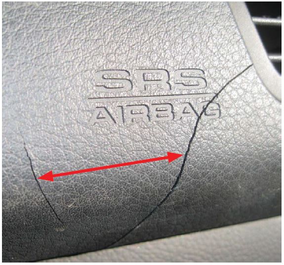
- On 2005-2009MY Legacy / Outback models, if any cracking is identified on either the outside “soft” padded surface of the IP as shown in the photo below or, if during disassembly, cracking of the internal “hard” plastic structure of the IP is found, the IP blocking procedure outlined in this bulletin must NOT be followed as more damage will likely result. In this case, the IP must be completely removed following the applicable Service Manual procedure before removing the airbag module.
- On the remaining models listed above, if any cracking of the internal structure of the IP is found, the IP MUST be completely removed before removing the airbag module. Using the blocking procedure will likely cause further damage to the IP.
- After CAREFULLY disengaging the retaining claws of the airbag module to remove it from the IP and again after reinstallation, ALL retaining holes must be inspected for any cracking.
- If cracks are found between the holes and leading edge or between the holes, the entire IP MUST Be replaced.
- Cracked or broken airbag retaining holes may affect the airbag’s proper deployment through the IP in the event of a crash.
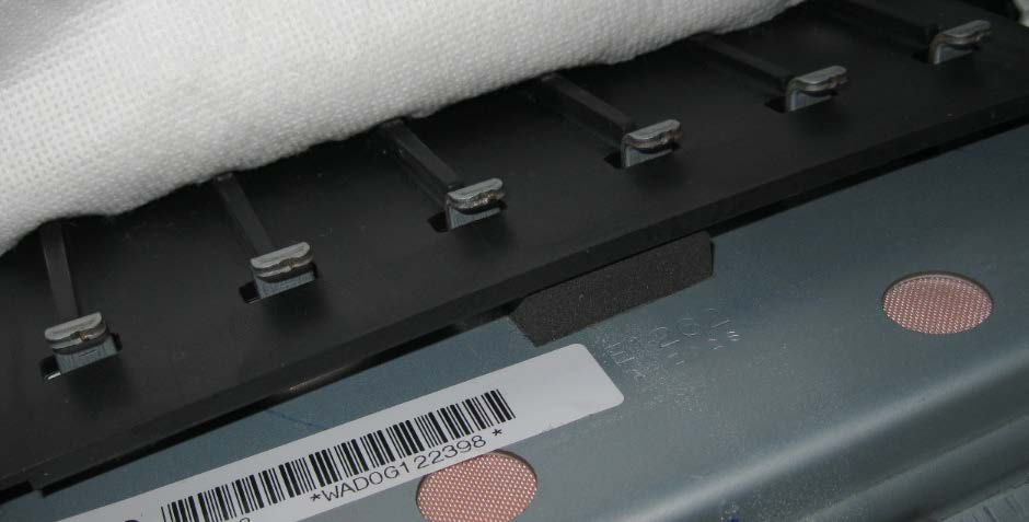
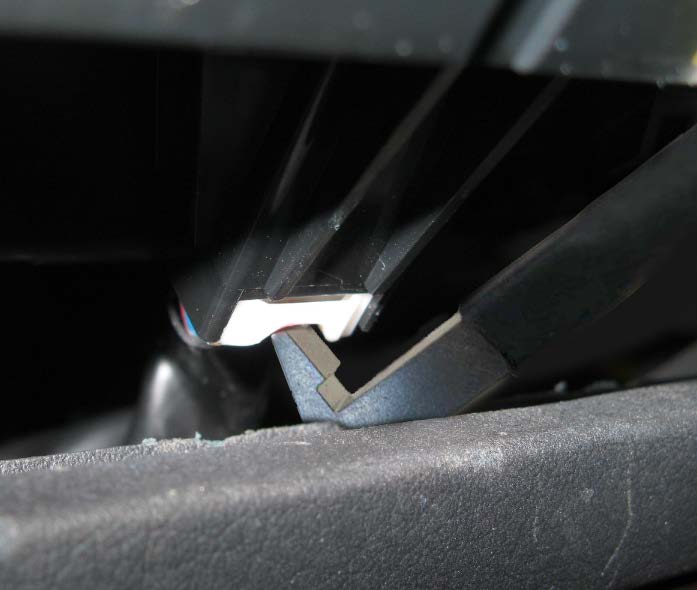
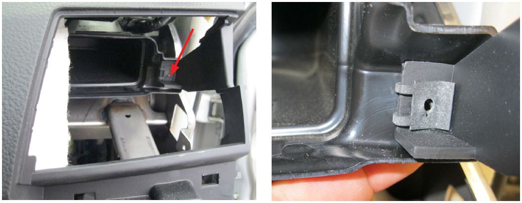
Module in position, retaining claws engaged.
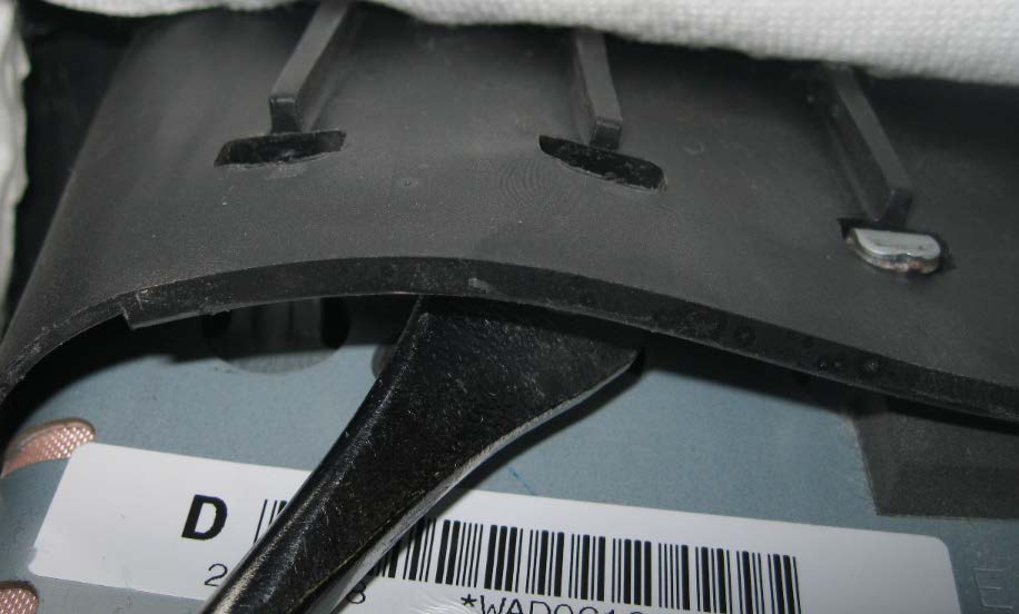
Retaining claws being CAREFULLY disengaged.
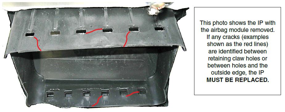
This photo shows the IP with the airbag module removed. If any cracks (examples shown as the red lines) are identified between retaining claw holes or between holes and the outside edge, the IP MUST BE REPLACED.
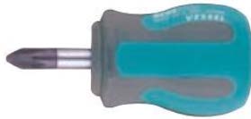
- To help make these repairs easier, two new tools as shown below have been developed and sent to Retailers automatically. Each retailer will be supplied two sets of these tools at no charge. A new removal tool, p.n. SOA635145 for removing the IP’s outside and center vent assemblies and, a resin block to support the IP on 2005-2009 Legacy and Outback models, p.n. SOA635146. There is also a velcro strap supplied along with the resin block to help hold it in position if needed when supporting the IP.
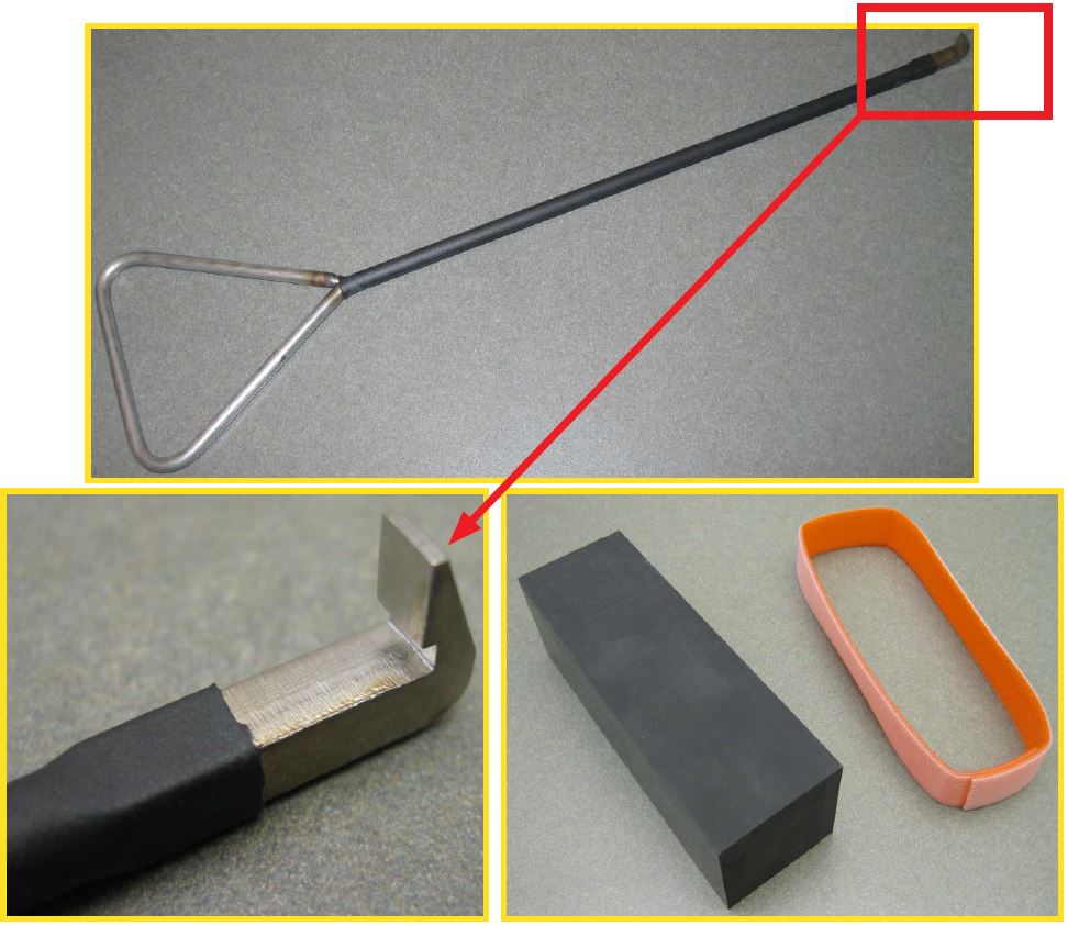
There will be some trial and error involved when learning how to use the new removal tool and getting the “feel” of it but, once proficient with the tool’s use, the effort will be well worth it in undamaged vent assemblies. Insert the removal tool into the vent being released and “feel” for the lip / edge where it fits inside the air supply duct.
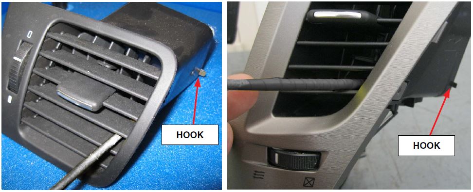
Once the inner lip / edge of the vent being removed is found (or “hooked”), pull firmly on the tool while applying outward force to keep it from slipping off. Once the first corner of the vent is released, move to the upper (or lower) corner and repeat. At this point, a plastic trim tool can be CAREFULLY used on the front of the vent trim as shown below to release and remove the vent the rest of the way. As stated previously, there will be trial and error until a “feel” for the tool is developed. PATIENCE is key!
The information will be broken up into 3 sections by model:
| 1. 2005-2009MY Legacy / Outback | Pg. 6 |
| 2. 2010-2014MY Legacy / Outback | Pg. 9 |
| 3. 2008-2011MY Impreza / WRX / STI and 2009-2013MY Forester. | Pg. 12 |
ADDITIONAL TOOLS NEEDED:
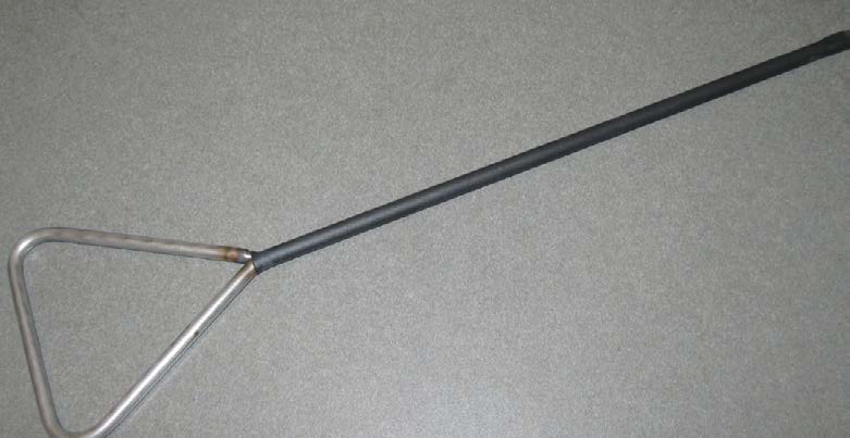
Removal Tool – For use on all models to assist with vent assembly removal and releasing the clock assembly wiring harness connector on 2005-2009MY Legacy / Outback.
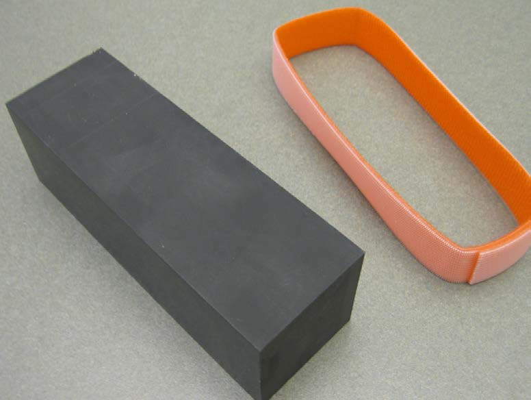
Resin Block and Velcro Strap – For use on 2005-2009MY Legacy / Outback to support the right (passenger) side of the IP while removing and reinstalling the airbag module. Use the Velcro strap to help hold the block in position as necessary.
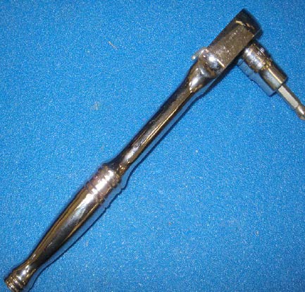
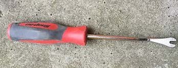
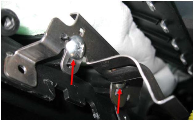
Ratchet and #2 Philips bit – This combination works the best for removing and reinstalling the air supply duct screw referenced in the 2005-2009MY Legacy / Outback procedure.
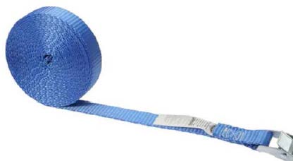
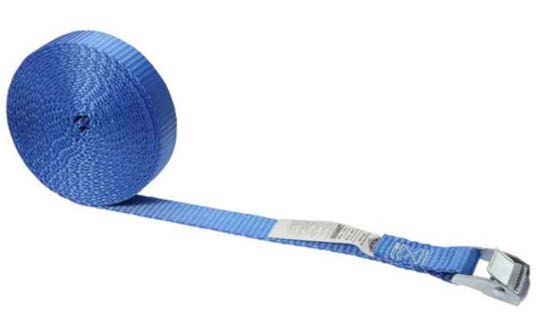
Cam-Buckle (tie-down) Strap (96” minimum length) – Used to support the IP while removing the airbag module on 2010-2014MY Legacy / Outback and Impreza and Forester models. These straps are readily available at most automotive retailers and online suppliers.
“Stubby” #2 Philips Screwdriver – Makes removing the air supply duct screw on 2010-14MY Legacy / Outback much easier.
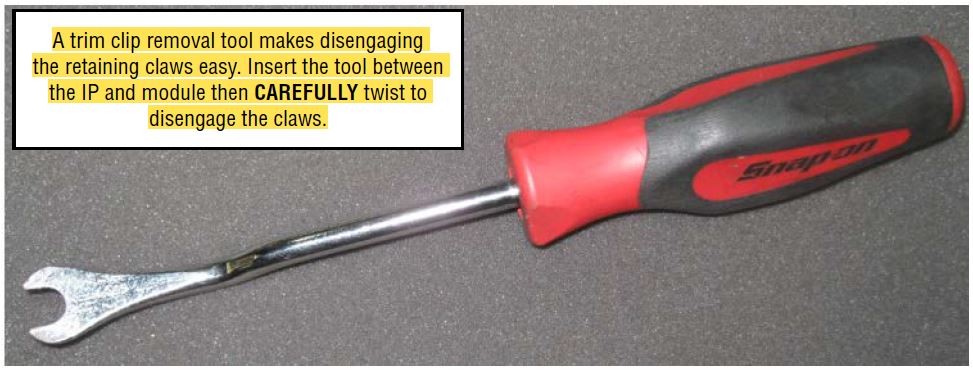
Trim Clip Removal Tool – Used for releasing the IP from the retaining claws on the airbag module on all applicable models.
1. SERVICE PROCEDURE TIPS FOR 2005-2009MY LEGACY / OUTBACK MODELS:
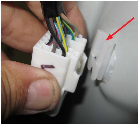
- The tool described above comes in handy when releasing the electrical connector for the clock on 2005-07 Legacy / Outback models due to the shorter length of the wiring harness. The 2008-09 models have a slightly longer harness which provides easier access to the connector.
REMINDER: On 2005-2009MY Legacy / Outback models, if any cracking is identified on either the outside “soft” padded surface of the IP or, if during disassembly, cracking of the internal “hard” plastic structure is found, the IP must be completely removed from the vehicle following the applicable Service Manual procedure before removing the airbag module.
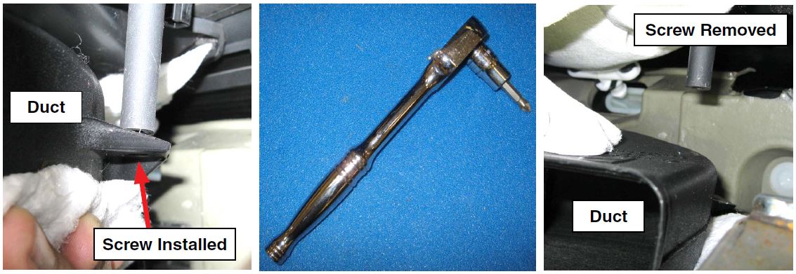
- Follow the Service Manual procedures for removing the IP but, once the IP is loose and moveable, support the passenger’s side end with the resin block as shown below. Use the velcro strap to hold the resin block in place if necessary.
- Lift the IP only as much as is needed to insert the resin block between the underside of the IP and the support brace on the steering column support bar as shown below.
- Once the resin block is in place, the Phillips screw securing the side vent air supply duct to the IP will be readily accessible. Remove the screw using a small ratchet and Phillips driver bit. Once this screw is removed, there will be more room making it easier to access the airbag module. NOTE: During reassembly, after installing the reinstalling the airbag module, this Phillips screw MUST be reinstalled to prevent a potential dash rattle.
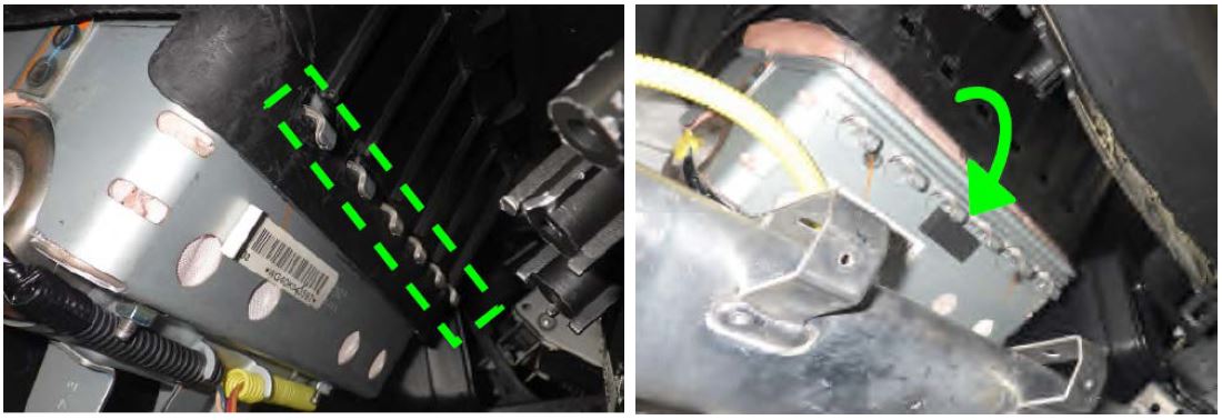
- On 2008-09MY models, there is an additional bracket secured by 2 Phillips screws which must be removed from the inside of the IP just above the glove box striker area.
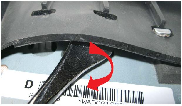
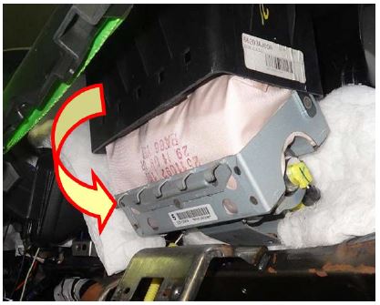
- While pushing upward on the airbag module, insert a trim clip removal tool (or large flat-blade) screwdriver in between the module and the IP and twist enough to CAREFULLY release the 6 “bottom” (easiest to see / access) claws as shown in the photo sequence below. It is not necessary to release the other 6 “top” side claws. Once the bottom claws are free, “rotate” the module downward and the rest will release on their own enabling it to be removed from the vehicle.
Module in position, retaining claws engaged. Retaining claws released and module rotated downward to release / remove.
IMPORTANT NOTES:
- When removing the airbag module, be careful to not damage the small harness for the sunload sensor (if equipped).
- After the airbag module is removed, inspect the retaining claw holes for any cracking that may have occurred during the removal. Refer to requirements for this inspection at the beginning of this bulletin.
- Always remove the resin block to allow the IP to “relax” while performing the inflator replacement procedure.
- Refer to applicable campaign bulletin for the inflator replacement procedures.
Once the inflator replacement procedure has been completed:
- After putting the resin block back in place, CAREFULLY reinstall the airbag module into the IP by engaging the top claws first then rotating the module upward to engage the bottom claws back into their holes. In some cases, the top of the airbag fabric itself may need to be tucked past the edge of the IP along with the corners of the module’s metal case to help the retaining claws “lock” back into their proper positions. When back in its proper position, there should be some slack or looseness felt between the module and the IP. If the module is tight after confirming all the retaining claws are fully engaged, it is likely the airbag itself is out of position. CAREFULLY remove the module again to inspect and reposition the airbag material as necessary. When the IP and module mounting hardware is tightened, this slack will be gone.
REMINDER: During reassembly, after installing the module, the Phillips screw securing the air supply duct MUST be reinstalled to prevent a potential dash rattle.
- The remainder of the procedure to reinstall the IP and related parts is completed by reversing the order of the disassembly instructions.
2. SERVICE PROCEDURE TIPS FOR 2010-2014MY LEGACY / OUTBACK MODELS:
- Although the Service procedure provided in the actual campaign bulletins states the IP must be removed, as long as there is no cracking in the structure of the IP, the airbag module can be accessed and removed without disconnecting all of the harness connectors and taking the IP completely out of the vehicle.
- The IP on these vehicles does not have a layer of soft padding on top of the structure like the earlier 2005-09MY Legacy / Outback. Although the outer surface has a texture, it is molded into the inner structure of the IP. In addition, the material the IP is made from is more pliable than the earlier models.
- Follow the Service Manual procedures for removing the IP.
- After the IP is loose and access is available from behind, remove the Phillips screw securing the air supply duct to its brace on the IP. Once this screw removed, there will be more room making it easier to access the airbag module. NOTE: During reassembly, after installing the module, this Phillips screw MUST be reinstalled to prevent a potential dash rattle.
- After removing the A-pillar trim, be careful when disconnecting the wiring harness to not damage the white plastic retaining clip as it is not available separately.
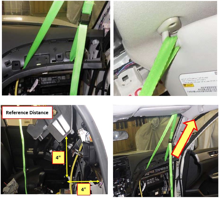
- The resin block referenced previously is NOT recommended for use on these vehicles. For these models, a readily available cam buckle / tie-down strap (96” minimum length, example shown below) is utilized to hold the IP in position for accessing, removing (and reinstalling) the airbag module once all the necessary components and attaching hardware has been removed.
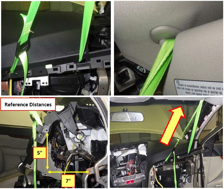
Use the photos below as a guide for positioning the support strap on the IP along with the upper securing point which is the mounting point for the sun visor.
IMPORTANT:
- To avoid damaging the visor, always make sure the opposite end of the visor closest to the rear view mirror is securely clipped into place before adding any load from the IP to
- The dimensions shown in the photos are the maximums needed to access and remove the module. To avoid damaging the IP, DO NOT EXCEED these dimensions.
- Once the IP is supported with the strap, CAREFULLY release the 5 airbag module retaining claws closest to the straps while using care to avoid adding more load to the visor. Rotate the module downward to remove it. ALWAYS release the strap to allow the IP to relax after the module is removed.
- Once the module has been removed, always inspect the retaining claw mounting holes for any damage as outlined at the start of this bulletin.
- Refer to applicable campaign bulletin for the inflator replacement procedures.
Once the inflator replacement procedure has been completed:
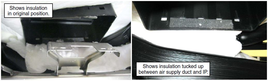
TIP: As shown in the photo below, there is a substantial amount of white poly-fill / insulation material around the airbag module location. Before reinstalling the module, CAREFULLY tuck the material up into the gap between the air supply duct and underside of the IP to get it out of the way of the “front” retaining claws. Once the module is locked back into position, reach up behind (ahead of) it, CAREFULLY pull the insulation back out and put it back into its original position.
- After repositioning the IP with the support strap, CAREFULLY reinstall the airbag module into the IP by engaging the top claws first then rotating the module upward to engage the bottom claws back into their holes. In some cases, the top of the airbag fabric itself may need to be tucked past the edge of the IP along with the corners of the module’s metal case to help the retaining claws “lock” back into their proper positions. When back in its proper position, there should be some slack or looseness felt between the module and the IP. If the module is tight after confirming all the retaining claws are fully engaged, it is likely the airbag itself is out of position. CAREFULLY remove the module again to inspect and reposition the airbag material as necessary. When the IP and module mounting hardware is tightened, this slack will be gone.
REMINDER: Always reinstall the air supply duct retaining screw.
- Inspect the claw holes for any cracking that may have occurred during reinstallation of the module and to ensure all claws are engaged. Refer to requirements for this inspection at the start of this bulletin.
- Release and remove the strap from the IP.
- The remainder of the procedure to reinstall the IP and related parts is completed by reversing the order of the disassembly instructions.
3. SERVICE PROCEDURE TIPS FOR 2008-2011MY IMPREZA, WRX / STI AND 2009-2013MY FORESTER MODELS:
- Although the Service procedure provided in the actual campaign bulletins states the IP must be removed, as long as there is no cracking in the structure of the IP, the airbag module can be accessed and removed without disconnecting all of the harness connectors and taking the IP completely out of the vehicle.
- Like the 2010-2014MY Legacy / Outback, the IP on these vehicles does not have a soft layer of padding on top of the structure like the earlier 2005-09MY Legacy / Outback. Although the outer surface has a texture, it is molded into the inner structure of the IP. In addition, the material the IP is made from is more pliable than the earlier models.
- Follow the Service Manual procedures for removing the IP but, once the IP is loose and moveable, support the passenger’s side end with a readily available cam buckle / tie-down support strap as previously outlined in the 2010-2014 Legacy / Outback procedure above.
- To avoid damaging the visor, always make sure the opposite end of the visor closest to the rear view mirror is securely clipped into place before adding any load from the IP to it.
- Once the support strap is installed through the holes on the IP, lift the end of the IP only as much as is needed without exceeding the Reference Distances as shown below.
- Once the support strap is in place with the IP supported, the Phillips screw securing the side vent air supply duct to the IP will be readily accessible. Remove the screw from the back using a small ratchet and Phillips driver bit or a “stubby” screw driver. Once this screw removed, there will be more room making it easier to access the airbag module. NOTE: During reassembly, after installing the module, this Phillips screw MUST be reinstalled to prevent a potential dash rattle.
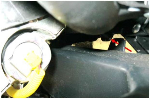
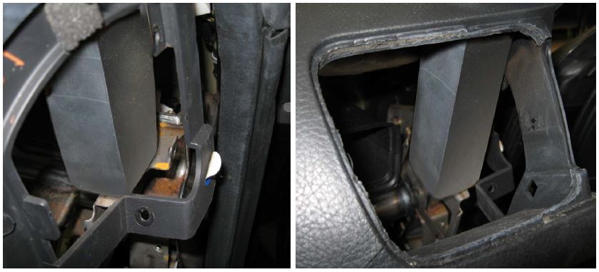
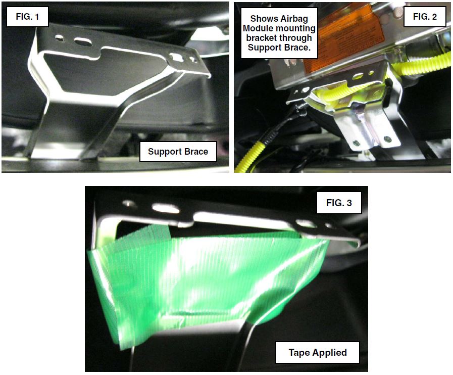
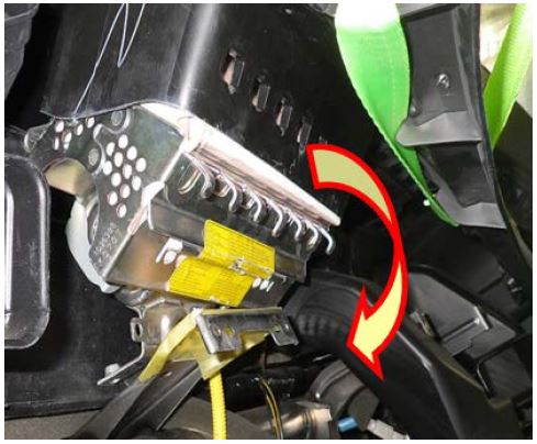
- On these models, there is an additional support brace for the IP attached to the steering column support bar ( 1 below). The bracket has an opening in it which the mounting bracket for the airbag module fits through easily. The airbag module cannot be removed if it’s mounting bracket becomes caught in this brace (Fig. 2). BEFORE attempting to remove the airbag module, apply a piece of duct tape (or equivalent) to the brace (Fig. 3) to prevent this.
- Once the IP is supported with the strap, CAREFULLY release the 5 airbag module retaining claws closest to the straps while using care to avoid adding more load to the visor. Rotate the module downward to remove it. ALWAYS release the strap to allow the IP to relax after the module is removed.
- Once the module has been removed, inspect the retaining claw mounting holes for any damage as outlined at the start of this bulletin.
- Refer to applicable campaign bulletin for the inflator replacement procedures.
Once the inflator replacement procedure has been completed:
- After re-supporting the IP with the strap, CAREFULLY reinstall the airbag module into the IP by engaging the top claws first then rotating the module upward to engage the bottom claws back into their holes. In some cases, the top of the airbag fabric itself may need to be tucked past the edge of the IP along with the corners of the module’s metal case to help the retaining claws “lock” back into their proper positions. When back in its proper position, there should be some slack or looseness felt between the module and the IP. If the module is tight after confirming all the retaining claws are fully engaged, it is likely the airbag itself is out of position. CAREFULLY remove the module again to inspect and reposition the airbag material as necessary. When the IP and module mounting hardware is tightened, this slack will be gone.
- Inspect the claw holes for any cracking that may have occurred during reinstallation of the module and to ensure all claws are engaged. Refer to requirements for this inspection at the start of this bulletin.
- REMINDER: Always reinstall the air supply duct retaining screw.
- Release and remove the strap from the IP.
- The remainder of the procedure to reinstall the IP and related parts is completed by reversing the order of the disassembly instructions.
IMPORTANT REMINDERS:
- SOA strongly discourages the printing and/or local storage of service information as previously released information and electronic publications may be updated at any time.
- Always check for any open recalls or campaigns anytime a vehicle is in for servicing.
- Always refer to STIS for the latest service informat
https://static.nhtsa.gov/odi/rcl/2016/RCRIT-16V358-5167.pdf
 Loading...

