
| “This site contains affiliate links for which OEMDTC may be compensated” |
Owner Manual
2017MY Legacy and Outback Owner’s Manual
MSA5M1703A
Table of contents
| Seat, seatbelt and SRS airbags | 1 |
| Keys and doors | 2 |
| Instruments and controls | 3 |
| Climate control | 4 |
| Audio | 5 |
| Interior equipment | 6 |
| Starting and operating | 7 |
| Driving tips | 8 |
| In case of emergency | 9 |
| Appearance care | 10 |
| Maintenance and service | 11 |
| Specifications | 12 |
| Consumer information and Reporting safety defects | 13 |
| Index | 14 |
MSA5M1703A
https://techinfo.subaru.com/stis/doc/ownerManual/MSA5M1703A_B_STIS_Index.pdf
https://static.oemdtc.com/OwnerManual/MSA5M1703A.pdf
 Loading...
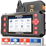
- 【Easy to Use--Work out of box】+【FOXWELL 2024 New Version】 FOXWELL NT604 Elite scan tool is the 2024 new version from FOXWELL, which is designed for those car owners who want to figure out the cause issue before fixing the car problem via scanning the most common systems like abs srs engine and transmission.The NT604 Elite diagnostic tool comes with latest software, which can be used out of box. No need to waste time to download the software first.
- 【Affordable】+【Reliable Car Health Monitor】 Will you be confused what happen when the warning light of abs/srs/transmission/check engine flashes? Instead of taking your cars to dealership, this foxwell scanner will help you do a thorough scanning and detection for your cars and pinpoint the root cause. It will t-urn off the warning light car after the problem is fixed.👉TIPS: Airbag crash/collision data can NOT be cleared even you replace the new airbag.
- 【5 in 1 Diagnostic Scanner】Compared with those auto scanners (50-100), NT604 Elite code scanner not only includes their OBDII diagnosis but also it can be an abs/srs scanner, transmission and check engine code reader. When it’s an odb2 scanner, you can use it to check if your car is ready for annual test through I/M readiness menu. In addition, live data stream, built-in DTC library, data play back and print, all these features are a big plus for it.
- 【Fantastic AUTOVIN】+【No extra software fee】Through the AUTOVIN menu, this NT604 Elite car scanner allows you to get your V-IN and vehicle info rapidly, no need to take time to find your V-IN and input one by one. What's more, the NT604 Elite abs srs scanner supports 60+ car makes from worldwide (America/Asia/Europe). You don’t need to pay extra software fee.
- 【Solid protective case KO plastic carrying bag】+ 【Lifetime update】Almost all same price-level obd scanner diagnostic tool only offers plastic bag to hold on the scanner.However, NT604 Elite automotive scanner is equipped with solid protective case, preventing your obd2 scanner from damage. Then you don’t need to pay extra money to buy a solid toolbox.

- 2024 Top Choice for ABS Bleeder Scan Tool - Is the brake pedal always slowly sinking down or becoming loose? This ABS brake bleeding scan tool will cycle the pump and valves to achieve a tight brake pedal. It's the most affordable obd2 scanner with ABS auto bleed. By following the instruction step by step, even a beginner can navigate through easily. Coverage check before purchasing via FOXWELL official site: Support- Diagnostic Coverage List. Tip: It won’t work on vehicles lacking an auto bleed function.
- More Than a Entry Level OBD2 Scanner, Ideal for Home Mechanics - Based on the NT301 FOXWELL Scanner, NT630 Plus takes OBD-II diagnostics to the next level by customizing functions for ABS and SRS system. This SRS and ABS scanner provides in-depth insights on error code diagnosis, wheel speed sensor, airbag circuits, cable connectors monitor, etc... Note: This scanner DOES NOT work on Airbag crash data/programming issues.
- No More Higher End Service than You Need - One NT630 Plus is enough! This obd2 scanner with ABS and SRS takes in-depth diagnosis on Anti-Lock Brake System & SRS/Airbag, and also performs Airbag light reset/ SAS(Steering Angle Sensor) adjustment/ Oil light reset daily reset services. These issues will be restored after the car faults repaired. Note: Some classic vehicles without the electronic control system can not support the reset service.
- Also can Work like NT301 - The NT630 Plus ABS code reader can connect to the OBD-II port directly. It will diagnose all OBD-II modules instantly, displays the live data, locates bad sensors and indicate I/M readiness status before the annual inspection. Guides you to do the maintenance work, reduces the potential driving risk and keep a peak performance on the road.
- Higher-level Services wih Lower Cost - Cost less to own a ABS SRS Bidirectional Scan Tool that is not found on similar code readers & scan tools. This car diagnostic scanner allows you to test all potential car faults in the ABS/Airbag system, with functions returning to normal once you exit the program. Please note, that only ABS/SRS modules are supported.

- [Transform Your Car Care Experience] - With BLCKTEC, instantly become your own professional mechanic. Effortlessly read and clear your car’s trouble codes and check engine light, ensuring your vehicle stays in top condition.
- [Empower Yourself with Comprehensive Diagnostics] - Unlock the full potential of your vehicle with the BLCKTEC 430. Access detailed diagnostics previously exclusive to professional mechanics’ OBD2 scan tools, including ABS, Airbag, SRS, TPMS codes, and beyond, right at your fingertips.
- [Drive with Confidence] - The BLCKTEC 430 is more than just a car code reader; it's your personal vehicle health advisor. Receive tailored repair reports with potential causes and verified solutions for your specific make and model, guiding you to the right fix every time.
- [Seamless Connectivity, Ultimate Convenience] - Experience the freedom of wireless diagnostics with this portable car scanner. Easily connect via Bluetooth to our intuitive sensor, and enjoy all the functionalities of high-end scan tools without the clutter of wires, directly from your smartphone or tablet.
- [DIY Repairs Made Easy] - Navigate car maintenance with ease using our premium app. Access a vast library of easy-to-follow repair videos, guiding you through each step of the repair process, compatible with both iOS & Android devices.

- 🎉【2024 Upgraded Ver. of AL519/ ML519/ ML619】Autel develops the brand-new AutoLink AL619 as the advanced ver. of Autel ML519, AL519, AL319, MS309. This AL619 OBD2 scanner can scan ABS & SRS systems, and support 10 Modes of OBD II Diagnostics Function on Worldwide Vehicles to read, erase codes and turn off the MIL, ABS, SRS warning lights so that you can better maintain your car when related malfunctions occur and make your vehicle ready for the annual test.
- 🎉【Accurate ABS/ SRS Diagnostics Functions】The ABS/ SRS diagnostic function is used to retrieve and clear codes from the ABS/ SRS systems. It can read and clear DTCs, show definitions of each code, display live data of multiple sensors in the graph to locate fault causes, and assist home mechanics to do the proper repair and clear ABS & Airbag warning lights. Diagnoses ABS/ SRS system codes on most 1996 and newer major vehicle models. Please email 📩 immoautel @ outlook. com 📩 for help.
- 🎉【All 10 Modes of OBD II Diagnostics Function】The OBD II Diagnostics function is a fast-access option that allows you to carry out a quick test on the engine system of OBD II vehicles. Read Codes, Erase Codes, Live Data, Freeze Frame, Retrieving I/M Readiness Status, O2 Monitor Test, On-Board Monitor Test, DTC Lookup, Component Test, Viewing Vehicle Information, Modules Present.
- 🎉【Live Data and Freeze Frame Data】With Live Data functions, Autel AL619 OBD2 diagnostic code reader allows you to view the live PID (Parameter Identification Data) of the vehicle's computer module(s) in text, graph to check the status of various sensors. And Freeze Frame Data enables you to view the vehicle's operating parameters at the moment a DTC is detected. These information will aid the technician by allowing the parameters to be duplicated for diagnostic and repair purposes.
- 🎉【DTC Lookup Feature】Besides showing you the code’s definition while you are reading the diagnostic trouble codes, AL619 features comparably user-friendly DTC Lookup Function which enables you to retrieve the definitions of any error codes from the large database of AL619, saving you from the hassle of wasting time searching definition of every code via Google.
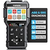
- [ABS & SRS Scanner with Active Test] The ABS/ SRS diagnostic tool Read & clear DTCs, displays live data in a graph to locate the cause of faults and assists the home mechanic with repairs and clearing ABS and airbag warning lights. Active test sensors, valves or solenoids etc. and tracks any threats in real time. It is invaluable to have a diagnostic tool with Active Test feature that you will never find on similar ABS/ SRS scanners.
- 【3 HOP Reset Services 】Easy to set up 3 regular reset services for Oil Light, Battery Management System, and Steering Angle Position. With this obd2 scanner, you can reset the oil service light and reset pre-programmed mileage intervals for energy efficiency; adjust or reset the steering angle position to keep steering aligned; and clear the original low battery fault information. No need to leave home for shop-quality car maintenance.
- 【All OBD2 Test Modes 】 This ABS & SRS scan tool is also a full featured obd2 code reader, allowing a quick test of the engine system of OBD II vehicles, can Read/Clear engine light codes, Live Data, Freeze Frame, Retrieving I/M Readiness Status, O2 Monitor Test, On-Board Monitor Test, Evap Test, Read Vehicle Information, and help pass smog test for most post-1996 OBD2/CAN vehicles.
- [DTC LookUp Library] Can't read the code? Go to the DTC LookUp Library. The Topdon AL600 OBD2 scanner offers a wealth of code definitions so you don't have to look them up in a list or database, and the HELP function takes you to diagnostic tips for possible fixes, saving time searching for repair materials online. No other scan tool or code reader under $100 offers this level of assistance.
- [User-Oriented] You'll love the feel of this automotive scanner, with black rubber grips all around the outer edges for durability and to withstand accidental drops. With its easy access menu, you can operate all functions in minutes with just a few button presses. The 3-color LEDs give you a intuitive indication of the OBD2 test results in a second. 3 shortcut keys, one key to read/clear DTCs and a one-touch smoke status check make it easy to use even for beginners.

- The VD500 OBD2 scanner is specifically designed to diagnose Volkswagen Group (Fits for VW/Audi/Skoda/ SEAT) 12-volt 16-pin vehicles, but can also be used with other 12-volt (non-Volkswagen) and light trucks (non-electric) vehicles manufactured in 1996 or later that are OBD II -compliant with standard 16-pin OBD II protocols (J1850 VPM, J1850PWM, ISO9141, KWP 2000 and CAN). Please send your vehicle information to our 💌amazon@anceltech.com💌 to check compatibility.
- For Volkswagen (VAG) vehicles diagnostics, the device can not only read and clear codes on engine, ABS, transmission, SAS (not all cars), ESP, TPMS and other systems, but also reset the oil, brake pad and throttle position adaption.
- For other OBD II vehicles (non-Volkswagen), the VD500 can read and clear fault codes, display fault code definitions, turn off the CEL (check engine light) and retrieve VIN information ONLY.
- The VD500 diagnostic offering for Volkswagen vehicles covers the following vehicles: fits for VW (CC, EOS, Golf, GTI, Jetta, Passat, Phaeton, Polo, Rabbit, Sharan, Tiguan, Touran, Touareg); fits for Audi (A3, A4, A6, A7, A8, A5, Q3, Q5, Q7, R8, RS3, TT, RS, RS5, S4, S6); fits for Skoda (Octavia, Rapid, Yeti, Kodiaq, Fabio, Superb); fits for SEAT (Leon, Ateca, Ibiza, Altea, Cushion, Cord, Alhambra) Diagnostics.
- With English and German as display languages, this diagnostic scan tool provides life-time free software updates to fix the latest bugs or add new parameters. Simply download the software from the official website, then follow on-screen instructions to install it.
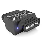
- [Pro OBD2 Scanner] - BlueDriver is the easiest way to scan and understand your vehicle like a professional mechanic. Read and clear your car’s trouble codes and check engine light.
- [Read & Clear All The Codes] - BlueDriver's enhanced vehicle diagnostics gives you access to information normally available only to mechanics on their OBD2 scan tools. Now you can read and clear ABS, Airbag, SRS, TPMS codes, and many more.
- [Get The Right Fix] - Much more than a car code reader, BlueDriver is a diagnostic tool. Get unlimited specific repair reports containing possible causes, reported fixes, and more for virtually every vehicle make and model.
- [Wireless & Bluetooth Enabled] - Say goodbye to wires. BlueDriver connects with Bluetooth via your phone/tablet to a sensor that plugs into your car's OBDII port. Get all of the capabilities of an expensive code reader & scan tool without any annoying wires.
- [User-Friendly App and Repair Videos] - BlueDriver gives you more ways to scan and fix your vehicle. Our iOS & Android app connects you to a large database of repair videos with step-by-step directions of repairs.

- 【Great Ideal For Every Car Owner】Prefect choice for your father, husband, brother or boyfriend. EVERY CAR OWNER WILL NEED IT! Also, the lifetime f-ree update is provided for more vehicle coverage, bug fixes. SAVE AT LEAST $1000+ PER YEAR!Get LAUNCH CRP123 Elite car diagnostic scanner and give your lover a surprise!Get the Extra Gifts :Protective Case Storage Bag,please reach us at: cardiag-aftersales @ hotmail.com.
- 【 Read & Clear/Reset Engine/ABS/SRS/Transmission Diagnostic Scan Tool 】LAUNCH CRP123 OBD2 Scanner can test Engine, Transmission, ABS and Airbag four systems, also reads and resets code, displays data stream graphic, stores and playbacks dynamic data stream,helps to quick analysis and diagnosis.
- 【 Error Fault Code Reader】Except the full 10 modes OBD2 diagnostic functions like, retrieving I/M readiness, Freeze Frame Data, Read Dynamic Data stream and V-ehicle Information, O2 Sensor Test, EVAP Test of F-uel Tank System (Mode 8) and Advanced On-board Monitoring (Mode 6), launch crp123 obd2 scanner can not only reveal what error codes your car is producing, but also erase your v-ehicle’s check engine light after problem fixed, the DTC help and explanation also tell you the exact problem.
- 【 Live Data Graphing + Read/Record/Playback Data stream + Print diagnostic data 】Live Data Graphing,more intuitive to know your vehicle’s problem.Large size Color Screen ;Print Function:Print the diagnose result easily; with user manual and register & update tutorial video uploaded in the link by us,you can Look up it anytime by ONE-CLICK.
- 【 Find Your Vehicles Here】Launch CRP123 obd2 scanner Supports mainstream vehicles on the world,fit for ACURA VW AUDI AUST FORD BENZ BMW CHRYSLER FIAT GM HOLDEN HONDA HYUNDAI INFINITI JAGUAR ISUZU KIA LANDROVER LEXUS MAZDA MITSUBISHI NISSAN OPEL PORSCHE SAAB SEAT SKODA SMART MERCEDES SPRINTER SUBARU SUZUKI SCION TOYOTA USA FORD VOLVO PEUGEOT CITROEN RENAULT EUROFORD.Etc.
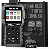
- ABS/SRS OBD2 Scanner > Enjoy this ABS SRS OBD2 code reader to reveal exact issues underlying in your brake, airbag, and engine systems, test individual ABS/SRS sensors, valves, or solenoids to quickly locate malfunctions (compatible with GM, Nissan, Fiat, Benz, Volvo, Land Rover, BMW, USA Ford, please reach us for details.), making sure critical safety systems work in perfect harmony together against accidents to be safe than sorry. NOTE: Only support upgrade on windows.
- 3 Most Needed Service Functions > This TOPDON OBD2 scanner guides you through step by step procedures to reset oil service light and programmed mileage intervals for engine efficiency (Oil Reset); to calibrate steering wheel position for vehicle’s traveling in a straight line (SAS Reset); to clear the original low battery fault information against coming battery failures or damage (BMS Reset); saving your needless visits to mechanics. NOTE: Not suitable for all models, please reach us for compatibility.
- Full OBD2 Diagnostics > Say goodbye to the hassle of manual check-ups via this srs bi-directional code reader. Quickly correct Check Engine Light warning on most OBD2/CAN compatible vehicles. Easily access to your smog status with one simple click I/M Readiness; and being filled with features for live data readings, freeze frame data, plus EVAP system, onboard monitor test means this scan tool checks all daily car care boxes.
- Work Easier > Red-Yellow-Green LEDs in this OBD2 diagnostic scanner TOPDON Arilink600 quickly show the overall DTC status without toggling through menu selections. HELP hotkey takes you directly to detailed descriptions/tips. Read/Erase DTC, I/M readiness shortcuts are added for optimized operation, along with DTC Lookup library for interpreting codes, designing the SRS OBD2 reader diagnostic tool a pleasure to use right out of the package even for beginners.
- Helpful Service > Get instant, free lifetime access to the most recent updates to add new car models and troubleshooting bugs making the OBD2 scanner TOPDON AL600 a long-term investment for any home mechanics. The extended 1 years of quality assurance sweetens the worry-free deal even further. Multilingual Menu: EN, FR, ES, DE, IT, RU, PT, and JP. NOTE: Only support upgrade on windows.

- [OBD2 Scanner] The TOPDON OBD2 scanner performs all ENG/AT/SRS/ABS diagnostics with 4-in-1 graphic live data. 🚩It covers all OBD2 tests for 67 manufacturers and 10000+ model. It also features 5-second one-touch AutoVIN, 🚩a free one-touch lifetime upgrade through WiFi, library DTC, 12 languages, 🚩printable auto-generated report with email sharing, 🚩smooth Android 11.0, 32GB ROM, 🚩vivid 5-inch touchscreen, and up to 10 hours of battery life.
- [4 Car System Code Reader] The TOPDON OBD2 scanner accesses 4 systems: 🚩Engine/ABS/SRS/Transmission. It identifies the ECU version, pull DTCs with 4-in-1 graphic live data and DTC explanation to identify issues, erase DTCs to turn off the warning lights after repair (For cars made in 2005 and newer). In order to help you extend the lifespan of your vehicle while improving performance, this code reader also includes all obd2 test modes to solve the major concerns for all vehicles.
- [User-Oriented TOPDON OBD2 Scanner] With this scan tool's touchscreen and rubberized buttons, you may easily navigate through menus or process while following a logical path. With 32GB on-board memory, the scanner enables for the recording of several diagnostic reports, which can be shared via email and printed for review. Along with this, you can 🚩upgrade your software for free for lifetime with one-touch over Wi-Fi for that help update the features and expanding car coverage.
- [Multiple Functions] The Smart AutoVIN of this TOPDON OBD2 scanner keeps track of your manual selections for vehicle make, model, and year and directs you to the suitable diagnostics. 🚩Max 4 Live Data streams integrated for much easier data processing. Diagnostic feedback online with this diagnostic tool to help you get tough repair operations well-completed. Real-time car battery voltage monitoring identifies probable vehicle defects.
- [Wide Coverage] With its multilingual menu and 🚩coverage of 67 car brands and 10,000+ models spanning North America, Europe, and Asia (including Malaysia, India, and Iran), this car scanner is compatible with the majority of 1996 and newer OBDII compliant automobiles (EN, FR, ES, DE, IT, RU, PT, JP, KR). Before buying, make sure the OBD2 scanner is compatible with your vehicle. The package contains only a charging cable and not a power adapter.
Last update on 2024-06-30 / Affiliate links / Images from Amazon Product Advertising API
This product presentation was made with AAWP plugin.
SEOCONTENT-START
Maintenance schedule . 11-3 Maintenance precautions. 11-3 Before checking or servicing in the engine compartment 11-4 When checking or servicing in the engine compartment (2.5 L models) . 11-5 When checking or servicing in the engine compartment while the engine is running 11-5 Maintenance tips 11-5 Removing and reinstalling clips 11-5 Engine hood . 11-7 Engine compartment overview 11-9 2.5 L models 11-9 3.6 L models 11-10 Engine oil 11-11 Engine oil consumption 11-11 Checking the oil level . 11-11 Changing the oil and oil filter 11-13 Recommended grade and viscosity 11-13 Synthetic oil. 11-13 Cooling system 11-14 Cooling fan, hose and connections. 11-14 Engine coolant . 11-15 Air cleaner element 11-15 Replacing the air cleaner element . 11-16 Spark plugs 11-18 Recommended spark plugs 11-18 Drive belts 11-18 Manual transmission oil 11-19 Recommended grade and viscosity 11-19 Continuously variable transmission fluid 11-19 Front differential gear oil (CVT models) and rear differential gear oil 11-19 Recommended grade and viscosity 11-19 Brake fluid 11-20 Checking the fluid level 11-20 Recommended brake fluid . 11-21 Clutch fluid (MT models) . 11-21 Checking the fluid level 11-21 Recommended clutch fluid. 11-22 Brake booster 11-22 Brake pedal 11-23 Checking the brake pedal free play 11-23 Checking the brake pedal reserve distance. 11-23 Clutch pedal (MT models) . 11-23 Checking the clutch function 11-23 Checking the clutch pedal free play 11-24 Replacement of brake pad 11-24 Breaking-in of new brake pads. 11-24 Tires and wheels 11-25 Types of tires. 11-25 Tire pressure monitoring system (TPMS) (if equipped) 11-25 Tire inspection. 11-27 Tire pressures and wear 11-27 Wheel balance . 11-29 Wear indicators . 11-29 Tire rotation direction mark 11-29 Tire rotation. 11-30 Tire replacement 11-30 Maintenance and service 11 Maintenance and service Wheel replacement. 11-31 Aluminum wheels. 11-32 Windshield washer fluid 11-32 Replacement of wiper blades 11-33 Windshield wiper blade assembly . 11-34 Windshield wiper blade rubber . 11-34 Rear window wiper blade assembly (Outback) . 11-35 Rear window wiper blade rubber (Outback) . 11-36 Battery. 11-37 Fuses 11-38 Installation of accessories. 11-40 Replacing bulbs . 11-40 HID headlights (if equipped) . 11-40 Halogen headlights 11-41 Front turn signal light 11-42 Front side marker light. 11-42 Front fog light (if equipped) 11-42 Rear combination lights . 11-44 Backup light 11-46 License plate light . 11-47 Dome light. 11-48 Map light . 11-48 Door step light. 11-49 Cargo area light (Outback) . 11-49 Trunk light (Legacy) . 11-49 Other bulbs . 11-49 Replacing battery. 11-50 Replacing battery of access key. 11-50 Replacing battery of transmitter . 11-51 Maintenance schedule U.S. models The scheduled maintenance items required to be serviced at regular intervals are shown in the “Warranty and Maintenance Booklet”. For details, read the separate “Warranty and Maintenance Booklet”. Canada models The scheduled maintenance items required to be serviced at regular intervals are shown in the “Warranty and Service Booklet”. For details, read the separate “Warranty and Service Booklet”. Except for U.S. and Canada models Some items of your vehicle are required to be serviced at scheduled intervals. For details about your maintenance schedule, read the separate “Warranty and Maintenance Booklet”. Maintenance precautions When maintenance and service are required, it is recommended that all work be done by an authorized SUBARU dealer. If you perform maintenance and service by yourself, you should familiarize yourself with the information provided in this section on general maintenance and service for your SUBARU. Incorrect or incomplete service could cause improper or unsafe vehicle operation. Any problems caused by improper maintenance and service performed by you are not eligible for warranty coverage. WARNING . Testing of an All-Wheel Drive vehicle must NEVER be performed on a single two-wheel dynamometer or similar apparatus. Attempting to do so will result in transmission damage and in uncontrolled vehicle movement and may cause an accident or injuries to persons nearby. . Always select a safe area when performing maintenance on your vehicle. . Always be very careful to avoid injury when working on the vehicle. Remember that some of the materials in the vehicle may be hazardous if improperly used or handled, for example, battery acid. . Your vehicle should only be serviced by persons fully competent to do so. Serious personal injury may result to persons not experienced in servicing vehicles. . Always use the proper tools and make certain that they are well maintained. . Never get under the vehicle supported only by a jack. Always use safety stands to support the vehicle. . Never keep the engine running in a poorly ventilated area, such as a garage or other closed areas. . Do not smoke or allow open flames around the fuel or battery. This will cause a fire. . Because the fuel system is under pressure, replacement of the fuel filter should be performed only by your SUBARU dealer. . Wear adequate eye protection to Maintenance and service/Maintenance schedule – CONTINUED – 11-3 Maintenance and service/Maintenance precautions guard against getting oil or fluids in your eyes. If something does get in your eyes, thoroughly wash them out with clean water. . Do not tamper with the wiring of the SRS airbag system or seatbelt pretensioner system, or attempt to take its connectors apart, as that may activate the system or it can render it inoperative. NEVER use a circuit tester for these wiring. If your SRS airbag or seatbelt pretensioner needs service, consult your nearest SUBARU dealer. NOTE SUBARU does not endorse the use of non-SUBARU approved flushing systems and strongly advises against performing these services on a SUBARU vehicle. Non-SUBARU approved flushing systems use chemicals and/or solvents which have not been tested or approved by SUBARU. SUBARU warranties do not cover any part of the vehicle which is damaged by adding or applying chemicals and/or solvents other than those approved or recommended by SUBARU. & Before checking or servicing in the engine compartment WARNING . Always stop the engine and apply the parking brake to prevent the vehicle from moving. . Always let the engine cool down. Engine parts become very hot when the engine is running and remain hot for some time after the engine is stopped. . Do not spill engine oil, engine coolant, brake fluid or any other fluid on hot engine components. This may cause a fire. . When the ignition switch is in the “ON” position, the cooling fan may operate suddenly even when the engine is stopped. If your body or clothes come into contact with a rotating fan, that could result in serious injury. To avoid risk of injury, perform the following precautions. – Models with push-button start system: Always turn the push-button ignition switch to the “OFF” position and confirm that the operation indicator on the switch is turned off. Then take the access key out from the vehicle. – Models without push-button start system: Always remove the key from the ignition switch. . Before performing any servicing on a vehicle equipped with a remote engine start system temporarily place that system in the service mode to prevent it from unexpectedly starting the engine. 11-4 & When checking or servicing in the engine compartment (2.5 L models) CAUTION . Do not contact the belt cover while checking the components in the engine compartment. Doing so may cause your hand to slip off the belt cover and result in an unexpected injury. . Do not touch the oil filter until the engine has cooled down completely. Doing so may result in a burn or other injury. Note that the oil filter becomes very hot when the engine is running and remains hot for some time after the engine has stopped. & When checking or servicing in the engine compartment while the engine is running WARNING A running engine can be dangerous. Keep your fingers, hands, clothing, hair and tools away from the cooling fan, belts and any other moving engine parts. Removing rings, watches and ties is advisable. Maintenance tips Some clips and fender linings must be removed before replacing the air cleaner elements or specific bulbs. & Removing and reinstalling clips ! Removing clips There are several types of clips used for your vehicle. ! Type A and D clips Type A clips Maintenance and service/Maintenance tips – CONTINUED – 11-5 Maintenance and service/Maintenance tips Type D clips 1. Turn the clips counterclockwise using a flat-head screwdriver until the center portion of the clip is raised. 2. Remove the clips with a flat-head screwdriver using leverage. ! Type B clips 1. Pull out the center portion of the clip using a flat-head screwdriver as shown in the illustration. 2. Pull the protruded center portion to remove the entire body of the clip. ! Type C clips 1. Turn the clip counterclockwise using a Phillips screwdriver until the center portion of the clip is raised. 2. Remove the entire clip by pulling it up. 11-6 ! Reinstalling clips Type A clips Type B clips Type C clips Type D clips Insert the clip without the center portion first and then push the center portion of the clip into the hole. Engine hood CAUTION . When you open the engine hood, do not stand the wiper blades up. Furthermore, while the hood is open, do not operate the windshield wipers. Doing so could result in damage to the engine hood and wiper blades. . Be extremely careful not to catch fingers or other objects when closing the engine hood. . Do not push the hood forcibly to close it. It could deform the metal. . Be extremely careful opening the engine hood when the wind is strong. The engine hood could close suddenly, possibly causing injuries from slamming. . Do not install accessories other than genuine SUBARU parts to the engine hood. If the engine hood becomes too heavy, the stay may not be able to support holding it open. Maintenance and service/Engine hood – CONTINUED – 11-7 Maintenance and service/Engine hood To open the hood: 1. If the wiper blades are lifted off the windshield, return them to their original positions. 2. Pull the hood lock release knob under the instrument panel. 3. Release the secondary hood lock by moving the lever between the front grille and the hood toward the left. 4. Lift up the hood. To close the hood: 1. Lower the hood to a height of approximately 5.9 in (15 cm) above its closed position and then throw it down. 2. After closing the hood, be sure the hood is securely locked. If this does not close the hood, release it from a slightly higher position. WARNING Always check that the hood is properly locked before you start driving. If it is not, it might fly open while the vehicle is moving and block your view, which may cause an accident and serious bodily injury. 11-8 Engine compartment overview & 2.5 L models 1) Brake fluid reservoir/Clutch fluid reservoir (MT) (page 11-20) 2) Fuse box (page 11-38) 3) Windshield washer tank (page 11-32) 4) Battery (page 11-37) 5) Engine oil filler cap (page 11-11) 6) Engine coolant reservoir (page 11-15) 7) Radiator cap (page 11-15) 8) Engine oil filter (page 11-13) 9) Engine oil level gauge (page 11-11) 10) Air cleaner case (page 11-15) Maintenance and service/Engine compartment overview – CONTINUED – 11-9 Maintenance and service/Engine compartment overview & 3.6 L models 1) Brake fluid reservoir (page 11-20) 2) Fuse box (page 11-38) 3) Windshield washer tank (page 11-32) 4) Battery (page 11-37) 5) Engine oil filler cap (page 11-11) 6) Engine coolant reservoir (page 11-15) 7) Radiator cap (page 11-15) 8) Engine oil level gauge (page 11-11) 9) Air cleaner case (page 11-15) 11-10 Engine oil CAUTION . If the level gauge is not pulled out easily, twist the level gauge right and left, then pull it out. Otherwise, you may be injured accidentally straining yourself. . Use only engine oil with the recommended grade and viscosity. . Be careful not to spill engine oil when adding it. If oil touches the exhaust pipe, it may cause a bad smell, smoke, and/or a fire. If engine oil gets on the exhaust pipe, be sure to wipe it off. & Engine oil consumption Some engine oil will be consumed while driving. The rate of consumption can be affected by such factors as transmission type, driving style, terrain and temperature. Under the following conditions, oil consumption can be increased and thus require refilling between maintenance intervals: . When the engine is new and within the break-in period . When the engine oil is of lower quality . When the incorrect oil viscosity is used . When engine braking is employed (repeatedly) . When the engine is operated at high engine speeds (for extended periods of time) . When the engine is operated under heavy loads (for extended periods of time) . When towing a trailer (Outback) . When the engine idles for extended periods of time . When the vehicle is operated in stop and go and/or heavy traffic situations . When the vehicle is used under severe thermal conditions . When the vehicle accelerates and decelerates frequently Under these or similar conditions, you should check your oil at least every 2nd fuel fill-up and change your engine oil more frequently. Different drivers in the same car may experience different results. If your oil consumption rate is greater than expected, contact your authorized SUBARU retailer who may perform a test under controlled conditions. & Checking the oil level 1. Park the vehicle on a level surface and stop the engine. If you check the oil level just after stopping the engine, wait a few minutes for the oil to drain back into the oil pan before checking the level. 2.5 L models 1) Oil level gauge 2) Oil filler cap 3) Oil filter Maintenance and service/Engine oil – CONTINUED – 11-11 Maintenance and service/Engine oil 3.6 L models 1) Oil level gauge 2) Oil filler cap CAUTION If the level gauge is not pulled out easily, twist the level gauge right and left, then pull it out. Otherwise, you may be injured accidentally straining yourself. 2. Pull out the level gauge, wipe it clean, and insert it again. 3. Be sure the level gauge is correctly inserted until it stops. 2.5 L models 1) Full level 2) Low level 3) Approximately 1.1 US qt (1.0 liter, 0.9 Imp qt) from low level to full level 3.6 L models 1) Full level 2) Low level 3) Approximately 1.1 US qt (1.0 liter, 0.9 Imp qt) from low level to full level 4. Pull out the oil level gauge again. 5. 2.5 L models: Check the oil levels on both sides of the level gauge. The engine oil level must be judged by the lowest of the two levels. If the oil level is below the low level mark, add oil so that the full level is reached. 3.6 L models: Check the oil level on the gauge. If the oil level is below the low level mark, add oil so that the full level is reached. 11-12 CAUTION . For 2.5 L models, be careful not to touch the engine oil filter when removing the oil filler cap. Doing so may result in a burn, a pinched finger, or may cause some other injury. . Use only engine oil with the recommended grade and viscosity. . Be careful not to spill engine oil when adding it. If oil touches the exhaust pipe, it may cause a bad smell, smoke, and/or a fire. If engine oil gets on the exhaust pipe, be sure to wipe it off. To add engine oil, remove the engine oil filler cap and slowly pour engine oil through the filler neck. After pouring oil into the engine, you must use the level gauge to confirm that the oil level is correct. NOTE To prevent overfilling the engine oil, do not add any additional oil above the full level when the engine is cold. & Changing the oil and oil filter Change the oil and oil filter according to the maintenance schedule in the “Warranty and Maintenance Booklet”. NOTE . Changing the engine oil and oil filter should be performed by a well-trained expert. Contact your SUBARU dealer for changing the engine oil and oil filter. Fully trained mechanics are on standby at a SUBARU dealer to utilize the special tools, spare parts and recommended oil for this work, and also, used oils are properly disposed of. . If performing oil replacement yourself, observe the local regulations and dispose of waste oil properly. & Recommended grade and viscosity CAUTION Use only engine oil with the recommended grade and viscosity. Refer to “Engine oil” F12-4. NOTE Engine oil viscosity (thickness) affects fuel economy. Oils of lower viscosity provide better fuel economy. However, in hot weather, oil of higher viscosity is required to properly lubricate the engine. & Synthetic oil You should use synthetic engine oil that meets the same requirements given for conventional engine oil. When using synthetic oil, you must use oil of the same classification, viscosity and grade shown in this Owner’s Manual. Refer to “Engine oil” F12-4. Also, you must follow the oil and filter changing intervals shown in the Warranty and Maintenance booklet. NOTE Synthetic oil of the grade and viscosity noted in chapter 12 is the recommended engine oil for optimum engine performance. Conventional oil may be used if synthetic oil is unavailable. Maintenance and service/Engine oil 11-13 Maintenance and service/Cooling system Cooling system WARNING Never attempt to remove the radiator cap until the engine has been shut off and has cooled down completely. Since the coolant is under pressure, you may suffer serious burns from a spray of boiling hot coolant when the cap is removed. CAUTION . Vehicles are filled at the factory with SUBARU Super Coolant that does not require the first change for 11 years/137,500 miles (11 years/220,000 km). This coolant should not be mixed with any other brand or type of coolant during this period. Mixing with a different coolant will reduce the life of the coolant. Should it be necessary to top off the coolant for any reason, use only SUBARU Super Coolant. If the SUBARU Super Coolant is diluted with another brand or type, the maintenance interval is shortened to that of the mixing coolant. . Do not splash the engine coolant over painted parts. The alcohol contained in the engine coolant may damage the paint surface. & Cooling fan, hose and connections Your vehicle employs an electric cooling fan which is thermostatically controlled to operate when the engine coolant reaches a specific temperature. 1) Normal operating range If the radiator cooling fan does not operate even when the engine coolant temperature gauge exceeds the normal operating range, the cooling fan circuit may be defective. Refer to “Temperature gauge” F3-12. Check the fuse and replace it if necessary. Refer to “Fuses” F11-38 and “Fuses and circuits” F12-10. If the fuse is not blown, have the cooling system checked by your SUBARU dealer. If frequent addition of coolant is necessary, there may be a leak in the engine cooling system. It is recommended that the cooling system and connections be checked for leaks, damage, or looseness. 11-14 & Engine coolant ! Checking the coolant level 1) “FULL” level mark 2) “LOW” level mark Check the coolant level at each fuel stop. 1. Check the coolant level on the outside of the reservoir while the engine is cool. 2. If the level is close to or lower than the “LOW” level mark, add coolant up to the “FULL” level mark. If the reserve tank is empty, remove the radiator cap and refill as required. 3. After refilling the reserve tank and the radiator, reinstall the caps and check that the rubber gaskets inside the radiator cap are in the proper position. CAUTION . Be careful not to spill engine coolant when adding it. If coolant touches the exhaust pipe, it may cause a bad smell, smoke, and/or a fire. If engine coolant gets on the exhaust pipe, be sure to wipe it off. . Do not splash the engine coolant over painted parts. The alcohol contained in the engine coolant may damage the paint surface. ! Changing the coolant It may be difficult to change the coolant. Have the coolant changed by your SUBARU dealer if necessary. The coolant should be changed according to the maintenance schedule in the “Warranty and Maintenance Booklet”. Air cleaner element WARNING Do not operate the engine with the air cleaner element removed. The air cleaner element not only filters intake air but also stops flames if the engine backfires. If the air cleaner element is not installed when the engine backfires, you could be burned. CAUTION When replacing the air cleaner element, use a genuine SUBARU air cleaner element. If it is not used, there is the possibility of causing a negative effect to the engine. The air cleaner element functions as a filter screen. When the element is perforated or removed, engine wear will be excessive and engine life shortened. The air cleaner element is a dry type. It is unnecessary to clean or wash the element. Maintenance and service/Air cleaner element – CONTINUED – 11-15 Maintenance and service/Air cleaner element & Replacing the air cleaner element Replace the air cleaner element according to the maintenance schedule in the “Warranty and Maintenance Booklet”. Under extremely dusty conditions, replace it more frequently. It is recommended that you always use genuine SUBARU parts. ! 2.5 L models 1) Clip 1. Unsnap the two clips holding the air cleaner case (rear). 2. Open the air cleaner case. 3. Remove the air cleaner element. CAUTION If the inside of the air cleaner case is extremely soiled (for example, by sand), contact a SUBARU dealer and have the air cleaner case cleaned. 4. If you find large foreign objects such as leaves inside the air cleaner case, remove the foreign objects. 5. Install a new air cleaner element in the way the longitudinal side and the transverse side face as shown in the illustration. 11-16 6. To install the air cleaner case (rear), insert the three projections on the air cleaner case (rear) into the slits on the air cleaner case (front). 7. Install in the reverse order of removal. ! 3.6 L models 1) Clips 1. Unsnap the two clips holding the air cleaner case (rear). 2. Open the air cleaner case and remove the air cleaner element. CAUTION If the inside of the air cleaner case is extremely soiled (for example, by sand), contact a SUBARU dealer and have the air cleaner case cleaned. 3. If you find large foreign objects such as leaves inside the air cleaner case, remove the foreign objects. 4. Install a new air cleaner element in the way the longitudinal side and the transverse side face as shown in the illustration. Maintenance and service/Air cleaner element – CONTINUED – 11-17 Maintenance and service/Spark plugs 5. To install the air cleaner case (rear), insert the three projections on the air cleaner case (rear) into the slits on the air cleaner case (front). 6. Install the removed parts in the reverse order of removal. Spark plugs It may be difficult to replace the spark plugs. It is recommended that you have the spark plugs replaced by your SUBARU dealer. The spark plugs should be replaced according to the maintenance schedule in the “Warranty and Maintenance Booklet”. & Recommended spark plugs Refer to “Electrical system” F12-9. Drive belts It is unnecessary to check the deflection of the drive belt periodically because your engine is equipped with an automatic belt tension adjuster. However, replacement of the belt should be done according to the maintenance schedule in the “Warranty and Maintenance Booklet”. Consult your SUBARU dealer for replacement. If the belt is loose, cracked or worn, contact your SUBARU dealer. 11-18 Manual transmission oil It is unnecessary to check the manual transmission oil level. However, if necessary, consult your SUBARU dealer for inspection. & Recommended grade and viscosity Each oil manufacturer has its own base oils and additives. Never use different brands together. For details, refer to “Manual transmission, front differential and rear differential gear oil” F12-7. Continuously variable transmission fluid There is no fluid level gauge. It is unnecessary to check the continuously variable transmission fluid level. However, if necessary, consult your SUBARU dealer for inspection. Front differential gear oil (CVT models) and rear differential gear oil It is not necessary to check the gear oil level. Check that there are no cracks, damage or leakage. However, the oil inspection should be performed according to the maintenance schedule in the “Warranty and Maintenance Booklet”. Consult your SUBARU dealer for details. & Recommended grade and viscosity Each oil manufacturer has its own base oils and additives. Never use different brands together. For details, refer to “Manual transmission, front differential and rear differential gear oil” F12-7. CAUTION Using a differential gear oil other than the specified oil may cause a decline in vehicle performance. Maintenance and service/Manual transmission oil 11-19 Maintenance and service/Brake fluid Brake fluid & Checking the fluid level WARNING . Never let brake fluid contact your eyes because brake fluid can be harmful to your eyes. If brake fluid gets in your eyes, immediately flush them thoroughly with clean water. For safety, when performing this work, wearing eye protection is advisable. . Brake fluid absorbs moisture from the air. Any absorbed moisture can cause a dangerous loss of braking performance. . If the vehicle requires frequent refilling, there may be a leak. If you suspect a problem, have the vehicle checked at your SUBARU dealer. CAUTION . When adding brake fluid, be careful not to allow any dirt into the reservoir. . Never splash the brake fluid over painted surfaces or rubber parts. Alcohol contained in the brake fluid may damage them. . Be careful not to spill brake fluid when adding it. If brake fluid touches the exhaust pipe, it may cause a bad smell, smoke, and/or a fire. If brake fluid gets on the exhaust pipe, be sure to wipe it off. The reservoir has two chambers, one for clutch fluid and the other for brake fluid. Each fluid level must therefore be checked in the appropriate chamber. Check the fluid level on the outside of the reservoir monthly. 3.6 L models 1) “MAX” level line 2) “MIN” level line A) The brake fluid level must be checked in this area. For 3.6 L models, be sure to check the brake fluid level on the outboard side of the reservoir (shaded area in the illustration). It cannot be checked on the inboard side of the reservoir. If the fluid level is below “MIN”, add the recommended brake fluid to “MAX”. Use only brake fluid from a sealed container. 11-20 2.5 L models 1) “MAX” level line 2) “MIN” level line A) The brake fluid level must be checked in this area. For 2.5 L models, be sure to check the brake fluid level at the front part of the reservoir (shaded area in the illustration). If the fluid level is below “MIN”, add the recommended brake fluid to “MAX”. Use only brake fluid from a sealed container. & Recommended brake fluid Refer to “Fluids” F12-8. CAUTION Never use different brands of brake fluid together. Also, avoid mixing DOT 3 and DOT 4 brake fluids even if they are the same brand. Clutch fluid (MT models) & Checking the fluid level WARNING Never let clutch fluid contact your eyes because clutch fluid can be harmful to your eyes. If clutch fluid gets in your eyes, immediately flush them thoroughly with clean water. For safety, when performing this work, wearing eye protection is advisable. CAUTION . Clutch fluid absorbs moisture from the air. Any absorbed moisture can cause improper clutch operation. . If the vehicle requires frequent refilling, there may be a leak. If you suspect a problem, have the vehicle checked at your SUBARU dealer. . When clutch fluid is added, be careful not to allow any dirt into the tank. . Never splash the clutch fluid over painted surfaces or rubber parts. Maintenance and service/Clutch fluid (MT models) – CONTINUED – 11-21 Maintenance and service/Brake booster Alcohol contained in the clutch fluid may damage them. . Be careful not to spill clutch fluid when adding it. If clutch fluid touches the exhaust pipe, it may cause a bad smell, smoke, and/or a fire. If clutch fluid gets on the exhaust pipe, be sure to wipe it off. . The fluid level for the clutch system must be checked at the inboard side of the reservoir. It cannot be checked at the outboard side of the reservoir. 1) “MAX” level line 2) “MIN” level line A) The clutch fluid level must be checked in this area. Check the fluid level monthly. Check the fluid level on the outside of the reservoir. Because this reservoir is used for both the brake and clutch systems and has chambers for each system, be sure to check the fluid level for the clutch system at the inboard side of the reservoir (shaded area in the illustration). If the fluid level is below “MIN”, add the recommended clutch fluid to “MAX”. Use only clutch fluid from a sealed container. & Recommended clutch fluid Refer to “Fluids” F12-8. CAUTION Never use different brands of clutch fluid together. Also, avoid mixing DOT 3 and DOT 4 brake fluids even if they are the same brand. Brake booster If the brake booster does not operate as described in the following procedure, have it checked by your SUBARU dealer. 1. With the engine off, depress the brake pedal several times, applying the same pedal force each time. The distance the pedal travels should not vary. 2. With the brake pedal depressed, start the engine. The pedal should move slightly down to the floor. 3. With the brake pedal depressed, stop the engine and keep the pedal depressed for 30 seconds. The pedal height should not change. 4. Start the engine again and run for approximately 1 minute then turn it off. Depress the brake pedal several times to check the brake booster. The brake booster operates properly if the pedal stroke decreases with each depression. 11-22 Brake pedal Check the brake pedal free play and reserve distance according to the maintenance schedule in the “Warranty and Maintenance Booklet”. & Checking the brake pedal free play 1) 0.02 – 0.11 in (0.5 – 2.7 mm) Stop the engine and firmly depress the brake pedal several times. Lightly pull the brake pedal up with one finger to check the free play with a force of less than 2 lbf (10 N, 1 kgf). If the free play is not within proper specification, contact your SUBARU dealer. & Checking the brake pedal reserve distance 1) More than 2.56 in (65 mm) Depress the pedal with a force of approximately 66 lbf (294 N, 30 kgf) and measure the distance between the upper surface of the pedal pad and the floor. When the measurement is smaller than the specification, or when the pedal does not operate smoothly, contact with your SUBARU dealer. Clutch pedal (MT models) Check the clutch pedal free play according to the maintenance schedule in the “Warranty and Maintenance Booklet”. & Checking the clutch function Check the clutch engagement and disengagement. 1. With the engine idling, check that there are no abnormal noises when the clutch pedal is depressed, and that shifting into 1st or reverse feels smooth. 2. Start the vehicle by releasing the pedal slowly to check that the engine and transmission smoothly couple without any sign of slippage. Maintenance and service/Brake pedal – CONTINUED – 11-23 Maintenance and service/Replacement of brake pad & Checking the clutch pedal free play 1) 0.19 – 0.44 in (5 – 11 mm) Lightly press the clutch pedal down with your finger until you feel resistance, and check the free play. If the free play is not within proper specification, contact your SUBARU dealer. Replacement of brake pad CAUTION . If you continue to drive despite the scraping noise from the audible brake pad wear indicator, it will result in the need for costly brake rotor repair or replacement. . It is recommended that you disconnect the vehicle battery before replacing the brake pad. However, it is dangerous to disconnect the vehicle battery. We recommend that you have your SUBARU dealer replace the brake pad. The disc brakes have audible wear indicators on the brake pads. If the brake pads wear close to their service limit, the wear indicator makes a very audible scraping noise when the brake pedal is applied. If you hear this scraping noise each time you apply the brake pedal, have the brake pads serviced by your SUBARU dealer as soon as possible. & Breaking-in of new brake pads When replacing the brake pad, use only genuine SUBARU parts. After replacement, the new parts must be broken in as follows: ! Brake pad While maintaining a speed of 30 to 40 mph (50 to 65 km/h), step on the brake pedal lightly. Repeat this five or more times. Also, apply and release the electronic parking brake five or more times. 11-24 Tires and wheels & Types of tires You should be familiar with type of tires present on your vehicle. ! All season tires The factory-installed tires on your new vehicle are all season tires. All season tires are designed to provide an adequate measure of traction, handling and braking performance in year-round driving including snowy and icy road conditions. However all season tires do not offer as much traction performance as winter (snow) tires in heavy or loose snow or on icy roads. All season tires are identified by “ALL SEASON” and/or “M+S” (Mud & Snow) on the tire sidewall. ! Summer tires Summer tires are high-speed capability tires best suited for highway driving under dry conditions. Summer tires are inadequate for driving on slippery roads such as on snowcovered or icy roads. If you drive your vehicle on snow-covered or icy roads, we strongly recommend the use of winter (snow) tires. When installing winter tires, be sure to replace all four tires. ! Winter (snow) tires Winter tires are best suited for driving on snow-covered and icy roads. However winter tires do not perform as well as summer tires and all season tires on roads other than snow-covered and icy roads. & Tire pressure monitoring system (TPMS) (if equipped) The tire pressure monitoring system provides the driver with a warning message by sending a signal from a sensor that is installed in each wheel when tire pressure is severely low. The tire pressure monitoring system will activate only when the vehicle is driven. Also, this system may not react immediately to a sudden drop in tire pressure (for example, a blow-out caused by running over a sharp object). If you adjust the tire pressures in a warm garage and will then drive the vehicle in cold outside air, the resulting drop in tire pressures may cause the low tire pressure warning light to illuminate. To avoid this problem when adjusting the tire pressures in a warm garage, inflate the tires to pressures higher than those shown on the tire placard. Specifically, inflate them by an extra 1 psi (6.9 kPa, 0.07 kgf/cm2) for every difference of 108F (5.68C) between the temperature in the garage and the temperature outside. By way of example, the following table shows the required tire pressures that correspond to various outside temperatures when the temperature in the garage is 608F (15.68C). Example: Tire size: 225/55R17 97V, 225/50R18 95H Standard tire pressures: Front: 33 psi (230 kPa, 2.3 kgf/cm2) Rear: 32 psi (220 kPa, 2.2 kgf/cm2) Garage temperature: 608F (15.68C) Outside temperature Adjusted pressure [psi (kPa, kgf/cm2)] Front Rear 308F (−18C) 36 (250, 2.5) 35 (240, 2.4) 108F (−128C) 38 (265, 2.65) 37 (255, 2.55) −108F (−238C) 40 (280, 2.8) 39 (270, 2.7) Example: Tire size: 225/65R17 102H, 225/60R18 100H Standard tire pressures: Front: 35 psi (240 kPa, 2.4 kgf/cm2) Rear: 33 psi (230 kPa, 2.3 kgf/cm2) Garage temperature: 608F (15.68C) Maintenance and service/Tires and wheels – CONTINUED – 11-25 Maintenance and service/Tires and wheels Outside temperature Adjusted pressure [psi (kPa, kgf/cm2)] Front Rear 308F (−18C) 38 (265, 2.65) 36 (250, 2.5) 108F (−128C) 40 (280, 2.8) 38 (265, 2.65) −108F (−238C) 42 (295, 2.95) 40 (280, 2.8) If the low tire pressure warning light illuminates when you drive the vehicle in cold outside air after adjusting the tire pressures in a warm garage, re-adjust the tire pressures using the method described above. Then, increase the vehicle speed to at least 20 mph (32 km/h) and check to see that the low tire pressure warning light goes off a few minutes later. If the low tire pressure warning light does not go off, the tire pressure monitoring system may not be functioning normally. In this event, go to a SUBARU dealer to have the system inspected as soon as possible. While the vehicle is driven, friction between tires and the road surface causes the tires to warm up. After illumination of the low tire pressure warning light, any increase in the tire pressures caused by an increase in the outside air temperature or by an increase in the temperature in the tires can cause the low tire pressure warning light to go off. System resetting is necessary when the wheels are changed (for example, a switch to snow tires) and new TPMS valves are installed on the newly fitted wheels. Have this work performed by a SUBARU dealer following wheel replacement. It may not be possible to install TPMS valves on certain wheels that are on the market. Therefore, if you change the wheels (for example, a switch to snow tires), use wheels that have the same part number as the standard-equipment wheels. Without four operational TPMS valve/sensors on the wheels, the TPMS will not fully function and the warning light in the instrument panel will illuminate steadily after blinking for approximately one minute. When a tire is replaced, adjustments are necessary to ensure continued normal operation of the tire pressure monitoring system. As with wheel replacement, therefore, you should have the work performed by a SUBARU dealer. WARNING If the low tire pressure warning light does not illuminate briefly after the ignition switch is turned ON or the light illuminates steadily after blinking for approximately one minute, you should have your Tire Pressure Monitoring System checked at a SUBARU dealer as soon as possible. If this light illuminates while driving, never brake suddenly. Instead, perform the following procedure. Otherwise an accident involving serious vehicle damage and serious personal injury could occur. 1) Keep driving straight ahead while gradually reducing speed. 2) Slowly pull off the road to a safe place. If this light still illuminates while driving after adjusting the tire pressure, a tire may have significant damage and a fast leak that causes the tire to lose air rapidly. If you have a flat tire, replace it with a spare tire as soon as possible. When a spare tire is mounted or a wheel rim is replaced without the original pressure sensor/transmitter being transferred, the low tire pressure warning light will illuminate steadily after blinking for approximately one minute. This indicates the TPMS is unable to monitor all four road wheels. Contact your 11-26 SUBARU dealer as soon as possible for tire and sensor replacement and/ or system resetting. If the light illuminates steadily after blinking for approximately one minute, promptly contact a SUBARU dealer to have the system inspected. & Tire inspection Check on a daily basis that the tires are free from serious damage, nails, and stones. At the same time, check the tires for abnormal wear. Contact your SUBARU dealer immediately if you find any problem. NOTE . When the wheels and tires strike curbs or are subjected to harsh treatment as when the vehicle is driven on a rough surface, they can suffer damage that cannot be seen with the naked eye. This type of damage does not become evident until time has passed. Try not to drive over curbs, potholes or on other rough surfaces. If doing so is unavoidable, keep the vehicle’s speed down to a walking pace or less, and approach the curbs as squarely as possible. Also, make sure the tires are not pressed against the curb when you park the vehicle. . If you feel unusual vibration while driving or find it difficult to steer the vehicle in a straight line, one of the tires and/or wheels may be damaged. Drive slowly to the nearest authorized SUBARU dealer and have the vehicle inspected. & Tire pressures and wear Maintaining the correct tire pressures helps to maximize the tires’ service lives and is essential for good running performance. Check and, if necessary, adjust the pressure of each tire (including the spare) at least once a month (for example, during a fuel stop) and before any long journey. Tire placard Check the tire pressures when the tires are cold. Use a pressure gauge to adjust the tire pressures to the values shown on the tire placard. The tire placard is located on the door pillar on the driver’s side. Driving even a short distance warms up the tires and increases the tire pressures. Also, the tire pressures are affected by the outside temperature. It is best to check tire pressure outdoors before driving the vehicle. When a tire becomes warm, the air inside it expands, causing the tire pressure to increase. Be careful not to mistakenly release air from a warm tire to reduce its pressure. NOTE . The air pressure in a tire increases by approximately 4.3 psi (30 kPa, 0.3 kgf/cm2) when the tire becomes warm. . The tires are considered cold when the vehicle has been parked for at least 3 hours or has been driven less than 1 mile (1.6 km). WARNING Do not let air out of warm tires to adjust pressure. Doing so will result in low tire pressure. Maintenance and service/Tires and wheels – CONTINUED – 11-27 Maintenance and service/Tires and wheels Incorrect tire pressures detract from controllability and ride comfort, and they cause the tires to wear abnormally. . Correct tire pressure (tread worn evenly) Roadholding is good, and steering is responsive. Rolling resistance is low, so fuel consumption is also lower. . Abnormally low tire pressure (tread worn at shoulders) Rolling resistance is high, so fuel consumption is also higher. . Abnormally high tire pressure (tread worn in center) Ride comfort is poor. Also, the tire magnifies the effects of road surface bumps and dips, possibly resulting in vehicle damage. WARNING Driving at high speeds with excessively low tire pressures can cause the tires to deform severely and to rapidly become hot. A sharp increase in temperature could cause tread separation, and destruction of the tires. The resulting loss of vehicle control could lead to an accident. 11-28 & Wheel balance Each wheel was correctly balanced when your vehicle was new, but the wheels will become unbalanced as the tires become worn during use. Wheel imbalance causes the steering wheel to vibrate slightly at certain vehicle speeds and detracts from the vehicle’s straight-line stability. It can also cause steering and suspension system problems and abnormal tire wear. If you suspect that the wheels are not correctly balanced, have them checked and adjusted by your SUBARU dealer. Also have them adjusted after tire repairs and after tire rotation. CAUTION Loss of correct wheel alignment causes the tires to wear on one side and reduces the vehicle’s running stability. Contact your SUBARU dealer if you notice abnormal tire wear. NOTE The suspension system is designed to hold each wheel at a certain alignment (relative to the other wheels and to the road) for optimum straight-line stability and cornering performance. & Wear indicators 1) New tread 2) Worn tread 3) Tread wear indicator Each tire incorporates a tread wear indicator, which becomes visible when the depth of the tread grooves decreases to 0.063 in (1.6 mm). A tire must be replaced when the tread wear indicator appears as a solid band across the tread. WARNING When a tire’s tread wear indicator becomes visible, the tire is worn beyond the acceptable limit and must be replaced immediately. With a tire in this condition, driving at high speeds in wet weather can cause the vehicle to hydroplane. The resulting loss of vehicle control can lead to an accident. NOTE For safety, inspect the tire tread regularly and replace the tires before their tread wear indicators become visible. & Tire rotation direction mark Example of tire rotation direction mark 1) Front If the tire has a rotation direction specification, the tire rotation direction mark is placed on its sidewall. When you install a tire that has the tire rotation direction mark, install the tire with Maintenance and service/Tires and wheels – CONTINUED – 11-29 Maintenance and service/Tires and wheels the direction mark facing forward. & Tire rotation Vehicles equipped with 4 non-unidirectional tires 1) Front Vehicles equipped with unidirectional tires 1) Front Tire wear varies from wheel to wheel. Move the tires to the positions shown in the illustration each time they are rotated. For the tire rotation schedule, refer to the “Warranty and Maintenance Booklet”. Replace any damaged or unevenly worn tire at the time of rotation. After tire rotation, adjust the tire pressures and make sure the wheel nuts are correctly tightened. After driving approximately 600 miles (1,000 km), check the wheel nuts again and retighten any nut that has become loose. & Tire replacement The wheels and tires are important and integral parts of your vehicle’s design; they cannot be changed arbitrarily. The tires fitted as standard equipment are optimally matched to the characteristics of the vehicle and were selected to give the best possible combination of running performance, ride comfort, and service life. It is essential for every tire to have a size and construction matching those shown on the tire placard and to have a speed symbol and load index matching those shown on the tire placard. Using tires of a non-specified size detracts from controllability, ride comfort, braking performance, speedometer accuracy and odometer accuracy. It also creates incorrect body-to-tire clearances and inappropriately changes the vehicle’s ground clearance. All four tires must be the same in terms of manufacturer, brand (tread pattern), construction, and size. You are advised to replace the tires with new ones that are identical to those fitted as standard equipment. For safe vehicle operation, SUBARU recommends replacing all four tires at the same time. 11-30 WARNING . When replacing or installing tire(s), all four tires must be the same for the following items. (a) Size (b) Circumference (c) Speed symbol (d) Load index (e) Construction (f) Manufacturer (g) Brand (tread pattern) (h) Degrees of wear For items (a) to (d), you must obey the specification that is printed on the tire placard. The tire placard is located on the driver’s door pillar. If all four tires are not the same in items (a) to (h), it may lead to serious mechanical damage to the drive train of your car and affect the following factors. — Ride — Handling — Braking — Speedometer/Odometer calibration — Clearance between the body and tires It also may be dangerous and lead to loss of vehicle control, and it can lead to an accident. . Use only radial tires. Do not use radial tires together with belted bias tires and/or bias-ply tires. Doing so can dangerously reduce controllability, resulting in an accident. & Wheel replacement When replacing wheels due, for example, to damage, make sure the replacement wheels match the specifications of the wheels that are fitted as standard equipment. Replacement wheels are available from SUBARU dealers. WARNING Use only those wheels that are specified for your vehicle. Wheels not meeting specifications could interfere with brake caliper operation and may cause the tires to rub against the wheel well housing during turns. The resulting loss of vehicle control could lead to an accident. Maintenance and service/Tires and wheels 11-31 Maintenance and service/Aluminum wheels Aluminum wheels Aluminum wheels can be scratched and damaged easily. Handle them carefully to maintain their appearance, performance, and safety. . When any of the wheels is removed and replaced for tire rotation or to change a flat, always check the tightness of the wheel nuts after driving approximately 600 miles (1,000 km). If any nut is loose, tighten it to the specified torque. . Never apply oil to the threaded parts, wheel nuts, or tapered surface of the wheel. . Never let the wheel rub against sharp protrusions or curbs. . When wheel nuts, balance weights, or the center cap is replaced, be sure to replace them with genuine SUBARU parts designed for aluminum wheels. Windshield washer fluid CAUTION Never use engine coolant as washer fluid because it could cause paint damage. Windshield washer fluid warning indicator When there is only a small amount of washer fluid remaining, the windshield washer fluid warning indicator will appear. When this occurs, refill the washer fluid as follows. 1) “FULL” mark Remove the washer tank filler cap, then add fluid until it reaches the “FULL” mark on the tank. Use windshield washer fluid. If windshield washer fluid is unavailable use clean water. In areas where water freezes in winter, use an anti-freeze type windshield washer fluid. SUBARU Windshield Washer Fluid contains 58.5% methyl alcohol and 41.5% surfactant, by volume. Its freezing temperature varies according to how much it is diluted, as indicated in the following table. 11-32 Washer Fluid Concentration Freezing Temperature 30% 10.48F (−128C) 50% −48F (−208C) 100% −498F (−458C) CAUTION Never use engine coolant as washer fluid because it could cause paint damage. In order to prevent freezing of washer fluid, check the freezing temperatures in the table above when adjusting the fluid concentration to the outside temperature. If you fill the reservoir tank with a fluid with a different concentration from the one used previously, purge the old fluid from the piping between the reservoir tank and washer nozzles by operating the washer for a certain period of time. Otherwise, if the concentration of the fluid remaining in the piping is too low for the outside temperature, it may freeze and block the nozzles. CAUTION . Adjust the washer fluid concentration appropriately for the outside temperature. If the concentration is inappropriate, sprayed washer fluid may freeze on the windshield and obstruct your view, and the fluid may freeze in the reservoir tank. . State or local regulations on volatile organic compounds may restrict the use of methanol, a common windshield washer antifreeze additive. Washer fluids containing non-methanol antifreeze agents should be used only if they provide cold weather protection without damaging your vehicle’s paint, wiper blades or washer system. Replacement of wiper blades Grease, wax, insects, or other materials on the windshield or the wiper blade results in jerky wiper operation and streaking on the glass. If you cannot remove the streaks after operating the windshield washer or if the wiper operation is jerky, clean the outer surface of the windshield (or rear window) and the wiper blades using a sponge or soft cloth with a neutral detergent or mild abrasive cleaner. After cleaning, rinse the windshield and wiper blades with clean water. The windshield is clean if beads do not form when you rinse the windshield with water. CAUTION . Do not clean the wiper blades with gasoline or a solvent, such as paint thinner or benzine. This will cause deterioration of the wiper blades. . When you wish to raise the passenger-side wiper arm, first raise the driver-side wiper arm. Otherwise, the passenger-side wiper assembly and driver-side wiper assembly will touch each other, possibly resulting in scratches. Maintenance and service/Replacement of wiper blades – CONTINUED – 11-33 Maintenance and service/Replacement of wiper blades . Return the passenger-side wiper arm to its original position before returning the driver-side wiper arm to its original position. Otherwise, the passenger-side wiper assembly and driver-side wiper assembly will touch each other, possibly resulting in scratches. . When returning the raised wipers to the original positions, return the wipers slowly on the windshield by hand. Returning the wipers from the detached positions by the spring operation might change the shape of the wiper arm or scratch the windshield. If you cannot eliminate the streaking even after following this method, replace the wiper blades using the following procedures. & Windshield wiper blade assembly NOTE Do not lower the wiper arm while the wiper blade assembly is removed. 1. Raise the wiper arm off the windshield. First raise the driver’s side wiper arm and then raise the front passenger’s side wiper arm. 1) Open the cover 2) Pull down the wiper blade 2. Remove the wiper blade assembly by opening the cover and pulling it down in the direction shown in the illustration. 3. Install the wiper blade assembly to the wiper arm. Make sure that it locks in place. 4. Hold the wiper arm by hand and slowly lower it into position. First lower the front passenger’s side wiper arm and then lower the driver’s side wiper arm. & Windshield wiper blade rubber 1) Support 1. Grasp the locked end of the blade rubber assembly and pull it firmly until the stoppers on the rubber are free of the support. 11-34 1) Metal spines 2. If the new blade rubber is not provided with two metal spines, remove the metal spines from the old blade rubber and install them in the new blade rubber. 3. Align the claws of the support with the grooves in the rubber and slide the blade rubber assembly into the support until it locks. 1) Claw 2) Stopper 4. Be sure to position the claws at the end of the support between the stoppers on the rubber as shown. If the rubber is not retained properly, the wiper blade may scratch the windshield. & Rear window wiper blade assembly (Outback) 1. Raise the wiper arm off the rear window. 2. Turn the wiper blade assembly counterclockwise. Maintenance and service/Replacement of wiper blades – CONTINUED – 11-35 Maintenance and service/Replacement of wiper blades 3. Pull the wiper blade assembly toward you to remove it from the wiper arm. & Rear window wiper blade rubber (Outback) 1. Pull out the end of the blade rubber assembly to unlock it from the plastic support. 2. Pull the blade rubber assembly out of the plastic support. 1) Metal spines 3. If the new blade rubber is not provided with two metal spines, remove the metal spines from the old blade rubber and install them in the new blade rubber. 11-36 4. Align the claws of the plastic support with the grooves in the blade rubber assembly, then slide the blade rubber assembly into place. Securely retain both ends of the rubber with the stoppers on the plastic support ends. If the rubber is not retained properly, the wiper may scratch the rear window glass. 5. Install the wiper blade assembly to the wiper arm. Make sure that it locks in place. 6. Hold the wiper arm by hand and slowly lower it in position. Battery WARNING . Before beginning work on or near any battery, be sure to extinguish all cigarettes, matches, and lighters. Never expose a battery to an open flame or electric sparks. Batteries give off a gas which is highly flammable and explosive. . For safety, in case an explosion does occur, wear eye protection or shield your eyes when working near any battery. Never lean over a battery. . Do not let battery fluid contact eyes, skin, fabrics, or paint because battery fluid is a corrosive acid. If battery fluid gets on your skin or in your eyes, immediately flush the area with water thoroughly. Seek medical help immediately if acid has entered the eyes. If battery fluid is accidentally swallowed, immediately drink a large amount of milk or water, and seek medical attention immediately. . To lessen the risk of sparks, Maintenance and service/Battery – CONTINUED – 11-37 Maintenance and service/Fuses remove rings, metal watchbands, and other metal jewelry. Never allow metal tools to contact the positive battery terminal and anything connected to it WHILE you are at the same time in contact with any other metallic portion of the vehicle because a short circuit will result. . Keep everyone including children away from the battery. . Charge the battery in a wellventilated area. . Battery posts, terminals, and related accessories contain lead and lead compounds, chemicals known to the State of California to cause cancer and reproductive harm. Batteries also contain other chemicals known to the State of California to cause cancer. Wash hands after handling. CAUTION Never use more than 10 amperes when charging the battery because it will shorten battery life. It is unnecessary to periodically check the battery fluid level or periodically refill with distilled water. Fuses CAUTION Never replace a fuse with one having a higher rating or with material other than a fuse because serious damage or a fire could result. The fuses are designed to melt during an overload to prevent damage to the wiring harness and electrical equipment. The fuses are located in two fuse boxes. One is located under the instrument panel behind the fuse box cover on the driver’s seat side. To remove the cover, pull it out. 11-38 The other one (main fuse box) is housed in the engine compartment. 1) Spare fuses The spare fuses are stored in the main fuse box cover in the engine compartment. The fuse puller is stored in the main fuse box in the engine compartment. To pick up the fuse puller, pull it out while pinching the puller head with your fingers. 1) Good 2) Blown If any lights, accessories or other electrical controls do not operate, inspect the corresponding fuse. If a fuse has blown, replace it. 1. Turn the ignition switch to the “LOCK”/ “OFF” position and turn off all electrical accessories. 2. Remove the fuse box cover. 3. Determine which fuse may be blown. Look at the back side of each fuse box cover and refer to “Fuses and circuits” F12-10. 4. Pull out the fuse with the fuse puller. 5. Inspect the fuse. If it has blown, replace it with a spare fuse of the same rating. 6. If the same fuse blows again, this indicates that its system has a problem. Maintenance and service/Fuses – CONTINUED – 11-39 Maintenance and service/Installation of accessories Contact your SUBARU dealer for repairs. Installation of accessories Always consult your SUBARU dealer before installing fog lights or any other electrical equipment in your vehicle. Such accessories may cause the electronic system to malfunction if they are incorrectly installed or if they are not suited for the vehicle. We recommend that you install only genuine SUBARU accessories on your vehicle. Replacing bulbs WARNING Bulbs may become very hot while illuminated. Before replacing bulbs, turn off the lights and wait until the bulbs cool down, Otherwise, there is the risk of sustaining a burn injury. CAUTION Replace any bulb only with a new bulb of the specified wattage. Using a bulb of different wattage could result in a fire. For the specified wattage of each bulb, refer to “Bulb chart” F12-14. For replacement, contact your SUBARU dealer. & HID headlights (if equipped) WARNING High-intensity-discharge (HID) bulbs are used for the low beams of the headlights. These HID bulbs use an extremely high voltage. To avoid the risk of an electric shock that could result in serious injury, observe the 11-40 following precautions. . Do not replace any headlight bulbs (both low beam and high beam) by yourself. . Do not remove/restore the headlight assemblies by yourself. . Do not remove any headlightassembly components by yourself. For replacement, contact your SUBARU dealer. & Halogen headlights CAUTION Halogen headlight bulbs become very hot while in use. If you touch the bulb surface with bare hands or greasy gloves, fingerprints or grease on the bulb surface will develop into hot spots, causing the bulb to break. If there are finger prints or grease on the bulb surface, wipe them away with a soft cloth moistened with alcohol. NOTE . If headlight aiming is required, consult your SUBARU dealer for proper adjustment of the headlight aim. . It may be difficult to replace the bulbs. Have the bulbs replaced by your SUBARU dealer if necessary. Perform the following steps to replace the bulbs. Low beam headlight (if equipped) 1) Electrical connector 2) Clip High beam headlight 1. Disconnect the electrical connector from the bulb. When replacing the low beam headlight bulb, remove the electrical connector from the clip before disconnecting the connector. Maintenance and service/Replacing bulbs – CONTINUED – 11-41 Maintenance and service/Replacing bulbs Low beam headlight (if equipped) High beam headlight 2. Remove the bulb from the headlight assembly by turning it counterclockwise. 3. Replace the bulb with new one. At this time, use care not to touch the bulb surface. 4. To install the bulb to the headlight assembly, turn it clockwise until it clicks. 5. Reconnect the electrical connector. & Front turn signal light 1. Turn the socket counterclockwise and pull it out. 2. Pull out the bulb from the socket and replace the bulb with a new one. & Front side marker light 1. Turn the socket counterclockwise and pull it out. 2. Pull out the bulb from the socket and replace the bulb with a new one. & Front fog light (if equipped) NOTE It may be difficult to replace the bulbs. We recommend that you have the bulbs replaced by your SUBARU dealer if necessary. 11-42 1. Remove the clips. 2. Turn over the mud guard. 3. Disconnect the electrical connector. Legacy Outback 4. Remove the bulb. 5. Replace the bulb with a new one. 6. After replacing the bulb, reattach the mud guard. Maintenance and service/Replacing bulbs – CONTINUED – 11-43 Maintenance and service/Replacing bulbs & Rear combination lights ! Legacy NOTE It may be difficult to replace the bulbs. We recommend that you have the bulbs replaced by your SUBARU dealer if necessary. 1. Turn the shopping bag hook 90 degrees counterclockwise and pull it out. 2. Turn over the trunk trim panel. 1) Rear side marker light 2) Rear turn signal light 3. Remove the bulb holder from the rear combination light assembly by turning it counterclockwise. Use pliers if necessary. 4. Pull the bulb out of the bulb holder and replace it with a new one. 5. Set the bulb holder into the rear combination light assembly and turn it clockwise until it locks. 6. Securely reposition the trunk trim panel. 7. Reattach the shopping bag hook. ! Outback 1. Undo the clips. For the method to undo the clips, refer to “Type C clips” F11-6. 2. Remove the cover. 11-44 3. Remove the upper and lower screws. 4. Slide the rear combination light assembly straight rearward and remove it from the vehicle. 1) Rear turn signal light 2) Rear side marker light 5. Remove the bulb holder from the rear combination light assembly by turning it counterclockwise. 6. Pull the bulb out of the bulb holder and replace it with a new one. 7. Set the bulb holder into the rear combination light assembly and turn it clockwise until it locks. 8. Reinstall the rear combination light assembly by sliding the two-pronged part of the combination light assembly securely to each holder of the vehicle side. 9. Tighten the upper and lower screws. 10. Reinstall the side cover. Maintenance and service/Replacing bulbs – CONTINUED – 11-45 Maintenance and service/Replacing bulbs & Backup light ! Legacy NOTE It may be difficult to replace the bulbs. We recommend that you have the bulbs replaced by your SUBARU dealer if necessary. 1. Open the trunk. 2. Remove the trunk trim lining by removing the clips indicated in the illustration. 3. Turn the bulb socket counterclockwise and remove it. 4. Pull the bulb out of the bulb socket and replace it with a new one. 5. Install the bulb socket by turning it clockwise. 6. Reconnect the electrical connector. 7. Reinstall the trunk trim lining. ! Outback 1. Apply a flat-head screwdriver to the light cover as shown in the illustration, and pry the light cover off from the rear gate trim. 11-46 2. Turn the bulb socket counterclockwise and remove it. 3. Pull the bulb out of the bulb socket and replace it with a new one. 4. Install the bulb socket by turning it clockwise. 5. Install the light cover on the rear gate. & License plate light ! Legacy NOTE It may be difficult to replace the bulbs. We recommend that you have the bulbs replaced by your SUBARU dealer if necessary. 1. Open the trunk. 2. Remove the trunk trim lining by removing the clips indicated in the illustration. 3. Turn the bulb socket counterclockwise and remove it. 4. Pull the bulb out of the bulb socket and replace it with a new one. 5. Install the bulb socket by turning it clockwise. 6. Reconnect the electrical connector. 7. Reinstall the trunk trim lining. Maintenance and service/Replacing bulbs – CONTINUED – 11-47 Maintenance and service/Replacing bulbs ! Outback 1. The license plate light must be pushed inwards, and then pulled out to be removed. 2. Turn the bulb socket counterclockwise and pull out the socket. 3. Pull the bulb out of the socket. 4. Install a new bulb. 5. Reinstall the bulb socket and the license plate light cover. & Dome light 1. Remove the lens by prying the edge of the lens with a flat-head screwdriver. 2. Turn the bulb until the flat surfaces at its ends are aligned vertically. 3. Pull the bulb straight downward to remove it. 4. Install a new bulb. 5. Reinstall the lens. & Map light CAUTION Replacing the bulb could cause burns since the bulb may be very hot. Have the bulb replaced by your SUBARU dealer. 11-48 & Door step light CAUTION Replacing the bulb could cause a short circuit. Have the bulb replaced by your SUBARU dealer. & Cargo area light (Outback) 1. Remove the lens by prying the edge of the lens with a flat-head screwdriver. 2. Pull the bulb out of the socket. 3. Install a new bulb. 4. Reinstall the lens. & Trunk light (Legacy) CAUTION Replacing the bulb could cause burns since the bulb may be very hot. Have the bulb replaced by your SUBARU dealer. & Other bulbs It may be difficult to replace the bulbs. We recommend that you have the bulbs replaced by your SUBARU dealer if necessary. Maintenance and service/Replacing bulbs 11-49 Maintenance and service/Replacing battery Replacing battery The access key / transmitter battery may be discharged under the following conditions. . The operation of the keyless access function is unstable . The operating distance of the remote keyless entry system is unstable . The transmitter does not operate properly when used within the standard distance Replace the battery with a new one. CAUTION . Do not let dust, oil or water get on or in the access key/transmitter when replacing battery. . Be careful not to damage the printed circuit board in the access key/transmitter when replacing the battery. . Be careful not to allow children to touch the battery and any removed parts; children could swallow them. . There is a danger of an explosion if the battery is incorrectly replaced. Replace only with the same or equivalent type of the battery. . Batteries shall not be exposed to excessive heat such as bright sunlight, fire or the like. NOTE . Replace only with the same or equivalent type of battery recommended by the manufacturer. . Dispose of used batteries according to the local laws. . Mount the battery in the correct orientation to prevent fluid leakage. Be careful not to bend the terminals. It may result in a malfunction. . It is recommended that the battery should be replaced by a SUBARU dealer. . Use a new battery. . After replacing the battery, confirm that the access key/transmitter functions properly. & Replacing battery of access key CAUTION When removing or fitting the access key cover, make sure that the plastic part does not come off or become misaligned. Battery: Button battery CR2032 1) Release button 2) Mechanical key 1. Take out the mechanical key. 11-50 2. Wrap a flat-head screwdriver with vinyl tape or a cloth, and insert it in the gap to remove the cover. 3. Take out the battery using a flat-head screwdriver with vinyl tape or a cloth. 4. Insert a new battery with its positive (+) side facing upward as shown in the figure. 5. Attach the cover to the access key by fitting the projections and recesses together. & Replacing battery of transmitter 1. Open the key head using a flat-head screwdriver. 2. Remove the transmitter case from the Maintenance and service/Replacing battery – CONTINUED – 11-51 Maintenance and service/Replacing battery key head. 3. Open the transmitter case by releasing the hooks. 1) Negative (−) side facing up 4. Replace the old battery with a new battery (Type CR1620 or equivalent) making sure to install the new battery with the negative (−) side facing up. 5. Put together the transmitter case by fitting the hooks on the case. 6. Reinstall the transmitter case in the key head. 7. Refit the removed half of the key head. After the battery is replaced, the transmitter must be synchronized with the remote keyless entry system’s control unit. Press either the “ ” or “ ” button six times to synchronize the unit. 11-52 Specifications. 12-2 Dimensions 12-2 Engine . 12-3 Fuel . 12-3 Engine oil 12-4 Manual transmission, front differential and rear differential gear oil . 12-7 Fluids 12-8 Engine coolant . 12-8 Electrical system 12-9 Tires 12-9 Brake disc . 12-9 Fuses and circuits . 12-10 Fuse panel located in the passenger compartment . 12-10 Fuse panel located in the engine compartment . 12-12 Bulb chart. 12-14 Safety precautions. 12-14 Bulb chart . 12-15 Vehicle identification . 12-18 Specifications 12 Specifications/Specifications Specifications These specifications are subject to change without notice. & Dimensions in (mm) Item Legacy Outback 2.5 L 3.6 L 2.5 L 3.6 L Drive system AWD Transmission type MT CVT CVT MT CVT CVT Overall length 188.8 (4,796) 189.6 (4,817) Overall width 72.4 (1,840) 72.4 (1,840) Overall height 59.0 (1,500) 66.1 (1,680)*2 65.2 (1,655)*3 64.0 (1,625)*4 Wheelbase 108.3 (2,750) 108.1 (2,745) Tread Front 62.2 (1,580) 61.8 (1,570) Rear 62.8 (1,595) 62.2 (1,580) Ground clearance*1 5.9 (150) 8.7 (220) *1: Measured with vehicle empty *2: Models with high profile roof rails *3: Models with low profile roof rails (U.S.-spec. models) *4: Models with low profile roof rails (except U.S.-spec. models) MT: Manual transmission CVT: Continuously variable transmission AWD: All-Wheel Drive 12-2 & Engine Engine model FB25 (2.5 L, DOHC, non-turbo) EZ36 (3.6 L, DOHC, non-turbo) Engine type Horizontally opposed, liquid cooled 4 cylinder, 4 stroke gasoline engine Horizontally opposed, liquid cooled 6 cylinder, 4 stroke gasoline engine Displacement cu-in (cc) 152 (2,498) 221.5 (3,630) Bore 6 Stroke in (mm) 3.70 6 3.54 (94.0 6 90.0) 3.62 6 3.58 (92.0 6 91.0) Compression ratio 10.3 : 1 10.5 : 1 Firing order 1 – 3 – 2 – 4 1 – 6 – 3 – 2 – 5 – 4 & Fuel Fuel requirement Fuel tank capacity Unleaded gasoline with 87 AKI (90 RON) or higher 18.5 US gal (70 liters, 15.4 Imp gal) Specifications/Specifications – CONTINUED – 12-3 Specifications/Specifications & Engine oil For the checking, adding and replacing procedure or other details, refer to “Engine oil” F11-11. NOTE The procedure for changing the engine oil and oil filter should be performed by a properly-trained expert. It is recommended that you have this service performed by your SUBARU dealer. ! Approved engine oil Always use the SUBARU approved engine oil. For further details, please contact your SUBARU dealer. If the approved engine oil is unavailable, use the alternative engine oil described on the next page. ! Alternative engine oil If the SUBARU approved oil is unavailable, the following alternative oil can be used. NOTE . Each quantity indicated is only a guideline. The necessary quantity for replacement may differ slightly depending on the temperature and other factors. . In choosing an oil, you want the proper quality and viscosity, as well as one that will enhance fuel economy. Oils of lower viscosity provide better fuel economy. However, in hot weather, oil of higher viscosity is required to properly lubricate the engine. The following table lists the recommended viscosities and applicable temperatures. . When adding oil, different brands may be used together as long as they are the same API classification and SAE viscosity as those recommended by SUBARU. 12-4 ! 2.5 L models Oil grade SAE viscosity No. and applicable temperature Engine oil capacity API (American Petroleum Institute) classification SN with the words “RESOURCE CONSERVING” or ILSAC (International Lubricant Specification Advisory Committee) GF-5, which can be identified with the ILSAC certification mark (Starburst mark) 0W-20 synthetic oil is the required oil for optimum engine performance and protection. Conventional oil may be used if synthetic oil is unavailable. *: If 0W-20 synthetic oil is not available, 5W-30 or 5W-40 conventional oil may be used if you need to add oil. However, you should change to 0W-20 synthetic oil at the next oil change. – Adding the oil from low level to full level: 1.1 US qt (1.0 liter, 0.9 Imp qt) – Changing the oil and oil filter: 5.1 US qt (4.8 liters, 4.2 Imp qt) Specifications/Specifications – CONTINUED – 12-5 Specifications/Specifications ! 3.6 L models Oil grade SAE viscosity No. and applicable temperature Engine oil capacity API (American Petroleum Institute) classification SN with the words “RESOURCE CONSERVING” or ILSAC (International Lubricant Specification Advisory Committee) GF-5, which can be identified with the ILSAC certification mark (Starburst mark) Your vehicle is designed to use 5W-30 conventional motor oil, however 5W-30 synthetic may be used for optimum engine performance. *: If 5W-30 synthetic oil is not available, 10W-30 or 10W-40 conventional oil may be used if you need to add oil. However, you should change to 5W-30 synthetic or conventional oil at the next oil change. – Adding the oil from L to F level: 1.1 US qt (1.0 liter, 0.9 Imp qt) – Changing the oil and oil filter: 6.9 US qt (6.5 liters, 5.7 Imp qt) 12-6 & Manual transmission, front differential and rear differential gear oil Oil Manual transmission oil Front differential gear oil (CVT models) Rear differential gear oil Oil grade . SUBARU Extra MT*3 . API classification GL-5 (75W-90)*4 API classification GL-5 SAE viscosity No. and applicable temperature — . 75W-90* . 90 *: Recommended Oil capacity*1 3.5 US qt (3.3 liters, 2.9 Imp qt) 2.5 L models: 1.3 US qt (1.2 liters, 1.1 Imp qt) 3.6 L models: 1.5 US qt (1.4 liters, 1.2 Imp qt) 0.8 US qt (0.8 liters, 0.7 Imp qt) Remarks*2 “Manual transmission oil” F11-19 “Front differential gear oil (CVT models) and rear differential gear oil” F11-19 “Front differential gear oil (CVT models) and rear differential gear oil” F11-19 *1: The indicated oil quantity is only a guideline. The necessary quantity for replacement may differ slightly depending on the temperature and other factors. After refilling the gearbox with oil, the oil level should be checked. *2: For more details about maintenance and service, refer to the indicated section. *3: The vehicle is filled at the factory with this type of manual transmission oil/front differential gear oil. *4: You may use this type of manual transmission oil/front differential gear oil. However, using this type of oil will detract from driveability and fuel efficiency. Specifications/Specifications – CONTINUED – 12-7 Specifications/Specifications & Fluids Fluid Fluid type*1 Fluid capacity*2 Remarks*3 Continuously variable transmission fluid (CVT models) Consult your SUBARU dealer. 2.5 L models: 12.0 US qt (11.4 liters, 10.0 Imp qt) 3.6 L models: 13.4 US qt (12.7 liters, 11.2 Imp qt) “Continuously variable transmission fluid” F11-19 Brake fluid FMVSS No. 116, fresh DOT 3 or DOT 4 brake fluid – “Brake fluid” F11-20 Clutch fluid (MT models) FMVSS No. 116, fresh DOT 3 or DOT 4 brake fluid – “Clutch fluid (MT models)” F11- 21 *1: Use one of the indicated types of fluid. *2: The indicated fluid quantity is only a guideline. The necessary quantity for replacement may differ slightly depending on the temperature and other factors. *3: For more details about maintenance and service, refer to the indicated section. & Engine coolant Vehicle model Coolant capacity Coolant type 2.5 L models MT models 8.0 US qt (7.6 liters, 6.7 Imp qt) CVT models 8.2 US qt (7.8 liters, 6.9 Imp qt) SUBARU Super Coolant 3.6 L models 7.4 US qt (7.0 liters, 6.2 Imp qt) The indicated coolant quantity is only a guideline. The necessary quantity for replacement may differ slightly depending on the temperature and other factors. For more details about maintenance and service, refer to “Cooling system” F11-14. 12-8 & Electrical system Battery type 2.5 L models except Canada-spec. models 55D23R Other models 75D23R Alternator 12V-130A Spark plugs 2.5 L models SILZKAR7B11 (NGK) 3.6 L models SILFR6C11 (NGK) & Tires Tire size 225/55R17 97V 225/50R18 95H 225/65R17 102H 225/60R18 100H Wheel size 17 6 7J 17 6 7 1/2J 18 6 7 1/2J 17 6 7J 18 6 7J Pressure Front 33 psi (230 kPa, 2.3 kgf/cm2) 35 psi (240 kPa, 2.4 kgf/cm2) Rear 32 psi (220 kPa, 2.2 kgf/cm2) 33 psi (230 kPa, 2.3 kgf/cm2) Temporary spare tire Size T155/70 D17 110M T155/80 R17 101M Pressure 60 psi (420 kPa, 4.2 kgf/cm2) Wheel nut tightening torque 88.5 lbf·ft (120 N·m, 12.2 kgf·m)*1 *1: This torque is equivalent to applying approximately 88 to 110 lbf (40 to 50 kgf) at the end of the wheel nut wrench. If you have tightened the wheel nuts by yourself, have the tightening torque checked at the nearest automotive service facility as soon as possible. For the wheel nut tightening procedure, refer to “Changing a flat tire” F9-5. & Brake disc If you need information on the usage limit value of brake discs and the method for measuring them, consult your SUBARU dealer. Specifications/Specifications 12-9 Specifications/Fuses and circuits Fuses and circuits & Fuse panel located in the passenger compartment Fuse panel Fuse rating Circuit 1 7.5A START1 2 20A 12V SOCKET 3 7.5A IG1-1 4 15A AUDIO NAVI 5 15A UNIT IG2-2 6 20A P/W R.LH 7 10A CIGAR 8 15A A/C IG 9 7.5A ACC 10 7.5A UNIT IG2-1 11 30A P/W MAIN1 12 7.5A START2 13 Empty 14 7.5A UNIT+B 15 7.5A METER IG 16 20A P/W R.RH 17 7.5A MIR 18 7.5A LAMP IG 19 7.5A IG1-2 20 10A SRS AIR BAG 21 20A P/W PASS1 22 15A SEAT HTR R 12-10 Fuse panel Fuse rating Circuit 23 10A DRL 24 20A P/W MAIN2 25 Empty 26 10A BACK UP 27 20A WIPER DEICER 28 20A TRAIL R.FOG 29 20A P/W PASS2 30 Empty 31 7.5A SMT 32 15A SEAT HTR F 33 7.5A KEY SW 34 7.5A D_OP+B 35 20A SUN ROOF 36 Empty 37 7.5A STOP 38 7.5A EYE SIGHT Specifications/Fuses and circuits – CONTINUED – 12-11 Specifications/Fuses and circuits & Fuse panel located in the engine compartment A) Main fuse Fuse panel Fuse rating Circuit 1 7.5A HORN RH 2 7.5A HORN LH 3 10A ILLUMI 4 10A TAIL 5 15A H/L LO RH 6 15A H/L LO LH 7 Empty 8 10A H/L HI LH 9 7.5A DCM 10 15A D/L 11 10A H/L HI RH 12 7.5A ALT-S 13 20A FUEL 14 15A HAZARD 15 30A IG2 16 7.5A PU B/UP 17 7.5A OBD 18 Empty 19 Empty 12-12 Fuse panel Fuse rating Circuit 20 20A*1 25A*2 O2 HTR 21 15A E/G2 22 15A ETC 23 15A E/G1 24 15A AVCS 25 15A INJ 26 7.5A CVT SSR 27 20A TCU 28 Empty 29 30A BACKUP 30 7.5A ACTGS 31 25A SUB FAN 32 25A MAIN FAN 33 30A ABS SOL 34 20A AUDIO 35 25A R.DEF 36 15A BLOWER 37 15A BLOWER 38 10A F.FOG RH 39 10A F.FOG LH 40 Empty 41 15A STRG/H Fuse panel Fuse rating Circuit 42 15A R.WIPER 43 15A F.WASH 44 30A F.WIPER 45 Empty *1: 2.5 L models *2: 3.6 L models Specifications/Fuses and circuits 12-13 Specifications/Bulb chart Bulb chart & Safety precautions WARNING . Bulbs may become very hot while illuminated. Before replacing bulbs, turn off the lights and wait until the bulbs cool down. Otherwise, there is a risk of sustaining a burn injury. . For models with HID low beam headlights, observe the following precautions. Not doing so carries the risk of an electric shock that could result in serious injury because the HID bulbs use an extremely high voltage. – Do not replace any headlight bulbs (both low beam and high beam) by yourself. – Do not remove/restore the headlight assemblies by yourself. – Do not remove any headlightassembly components by yourself. For replacement, contact your SUBARU dealer. CAUTION Replace any bulb only with a new bulb of the specified wattage. Using a bulb of different wattage could result in a fire. 12-14 & Bulb chart NOTE Lights A, B, C, D, E and F are the LED (Light Emitting Diode) type. Consult your SUBARU dealer for replacement. Specifications/Bulb chart – CONTINUED – 12-15 Specifications/Bulb chart Wattage Bulb No. 1) High beam headlight 12V-60W HB3 2) Low beam headlight Models with HID headlights 12V-35W D4S Models without HID headlights 12V-55W H11 3) Front side marker light 12V-5W W5W 4) Map light 12V-8W 5) Dome light 12V-8W 6) Door step light 12V-5W W5W 7) Front turn signal light 12V-21W WY21W 8) Front fog light Legacy (models without steering responsive fog lights system) 12V-19W H16 Legacy (models with steering responsive fog lights system) 12V-55W H11 Outback 12V-55W H11 9) Vanity mirror light 14V-1.4W HTU 10) Cargo area light 12V-13W SAE #912 11) Licence plate light (Outback) 12V-5W W5W 12) Backup light (Outback) 12V-16W W16W 13) Rear turn signal light (Outback) 12V-21W WY21W 14) Rear side marker light (Outback) 12V-5W W5W 15) Trunk light (Legacy) 12V-3.8W SAE #194 16) License plate light (Legacy) 12V-5W W5W 17) Backup light (Legacy) 12V-16W W16W 12-16 Wattage Bulb No. 18) Rear turn signal light (Legacy) 12V-21W WY21W 19) Rear side marker light (Legacy) 12V-5W W5W A) Parking light – – B) Side turn signal light (if equipped) – – C) High-mounted stop light (Outback) – – D) Tail and stop light (Outback) – – E) High-mounted stop light (Legacy) – – F) Tail and stop light (Legacy) – – Specifications/Bulb chart 12-17 Specifications/Vehicle identification Vehicle identification 1) Emission control label 2) Certification and bar code label 3) Tire inflation pressure label 4) Vehicle identification number plate 5) Model number label 6) Fuel label 7) Air conditioner label 12-18 For U.S.A. . 13-2 Tire information 13-2 Tire labeling . 13-2 Recommended tire inflation pressure 13-4 Glossary of tire terminology . 13-5 Tire care – maintenance and safety practices 13-9 Vehicle load limit – how to determine 13-10 Determining compatibility of tire and vehicle load capacities . 13-13 Adverse safety consequences of overloading on handling and stopping and on tires . 13-13 Steps for Determining Correct Load Limit. 13-14 Uniform tire quality grading standards 13-14 Treadwear . 13-15 Traction AA, A, B, C. 13-15 Temperature A, B, C. 13-15 Reporting safety defects (USA) 13-16 Consumer information and Reporting safety defects 13 Consumer information and Reporting safety defects/For U.S.A. For U.S.A. The following information has been compiled according to Code of Federal Regulations “Title 49, Part 575”. Tire information & Tire labeling Many markings (e.g. Tire size, Tire Identification Number or TIN) are placed on the sidewall of a tire by tire manufacturers. These marking can provide you with useful information on the tire. ! Tire size Your vehicle comes equipped with P-Metric tire size. It is important to understand the sizing system in selecting the proper tire for your vehicles. Here is a brief review of the tire sizing system with a breakdown of its individual elements. ! P Metric With the P-Metric system, Section Width is measured in millimeters. To convert millimeters into inches, divide by 25.4. The Aspect Ratio (Section Height divided by Section Width) helps provide more dimensional information about the tire size. Example: (1) P = Certain tire type used on light duty vehicles such as passenger cars (2) Section Width in millimeters (3) Aspect Ratio (= section height 7 section width). (4) R = Radial Construction (5) Rim diameter in inches ! Load and Speed Rating Descriptions The load and speed rating descriptions will appear following the size designation. They provide two important facts about the tire. First, the number designation is its load index. Second, the letter designation indicates the tire’s speed rating. 13-2 Example: (6) Load Index: A numerical code which specifies the maximum load a tire can carry at the speed indicated by its speed symbol, at maximum inflation pressure. For example, “91” means 1,356 lbs (615 kg), “90” means 1,323 lbs (600 kg), “89” means 1,279 lbs (580 kg) WARNING Load indices apply only to the tire, not to the vehicle. Putting a load rated tire on any vehicle does not mean the vehicle can be loaded up to the tire’s rated load. (7) Speed Rating: An alphabetical system describing a tire’s capability to travel at established and predetermined speeds. For example, “V” means 149 mph (240 km/h) WARNING . Speed ratings apply only to the tire, not to the vehicle. Putting a speed rated tire on any vehicle does not mean the vehicle can be operated at the tire’s rated speed. . The speed rating is void if the tires are worn out, damaged, repaired, retreaded, or otherwise altered from their original condition. If tires are repaired, retreaded, or otherwise altered, they may not be suitable for original equipment tire designed loads and speeds. ! Tire Identification Number (TIN) Tire Identification Number (TIN) is marked on the intended outboard sidewall. The TIN is composed of four groups. Here is a brief review of the TIN with a breakdown of its individual elements. (1) Manufacturer’s Identification Mark (2) Tire Size (3) Tire Type Code (4) Date of Manufacture The first two figures identify the week, starting with “01” to represent the first full week of the calendar year; the second two figures represent the year. For example, 0101 means the 1st week of 2001. ! Other markings The following makings are also placed on the sidewall. ! Maximum permissible inflation pressure The maximum cold inflation pressure to which this tire may be inflated. For example, “350 kPa (51 PSI) MAX. PRESS” Consumer information and Reporting safety defects/Tire information – CONTINUED – 13-3 Consumer information and Reporting safety defects/Tire information ! Maximum load rating The load rating at the maximum permissible weight load for this tire. For example, “MAX. LOAD 615 kg (1,356 LBS) @ 350 kPa (51 PSI) MAX. PRESS.” WARNING Maximum load rating applies only to the tire, not to the vehicle. Putting a load rated tire on any vehicle does not mean the vehicle can be loaded up to the tire’s rated load. ! Construction type Applicable construction of this tire. For example, “TUBELESS STEEL BELTED RADIAL” ! Construction The generic name of each cord material used in the plies (both sidewall and tread area) of this tire. For example, “PLIES: TREAD 2 STEEL + 2 POLYESTER + 1 NYLON SIDEWALL 2 POLYESTER” ! Uniform Tire Quality Grading (UTQG) For details, refer to “Uniform tire quality grading standards” F13-14. & Recommended tire inflation pressure ! Recommended cold tire inflation pressure For the recommended cold tire inflation pressure for your vehicle’s tires, refer to “Tires” F12-9. ! Vehicle placard The vehicle placard is affixed to the driver’s side B-pillar. Example: 13-4 The vehicle placard shows original tire size, recommended cold tire inflation pressure on each tire at maximum loaded vehicle weight, seating capacity and loading information. ! Adverse safety consequences of under-inflation Driving at high speeds with excessively low tire pressures can cause the tires to flex severely and to rapidly become hot. A sharp increase in temperature could cause tread separation, and failure of the tire(s). Possible resulting loss of vehicle control could lead to an accident. ! Measuring and adjusting air pressure to achieve proper inflation Check and, if necessary, adjust the pressure of each tire (including the spare) at least once a month and before any long journey. Check the tire pressures when the tires are cold. Use a pressure gauge to adjust the tire pressures to the specific values. Driving even a short distance warms up the tires and increases the tire pressures. Also, the tire pressures are affected by the outside temperature. It is best to check tire pressure outdoors before driving the vehicle. When a tire becomes warm, the air inside it expands, causing the tire pressure to increase. Be careful not to mistakenly release air from a warm tire to reduce its pressure. & Glossary of tire terminology . Accessory weight The combined weight (in excess of those standard items which may be replaced) of automatic transmission, power steering, power brakes, power windows, power seats, radio, and heater, to the extent that these items are available as factory-installed equipment (whether installed or not). . Bead The part of the tire that is made of steel wires, wrapped or reinforced by ply cords and that is shaped to fit the rim. . Bead separation A breakdown of the bond between components in the bead. . Bias ply tire A pneumatic tire in which the ply cords that extend to the beads are laid at alternate angles substantially less than 90 degrees to the centerline of the tread. . Carcass The tire structure, except tread and sidewall rubber which, when inflated, bears the load. . Chunking The breaking away of pieces of the tread or sidewall. . Cold tire pressure The pressure in a tire that has been driven less than 1 mile or has been standing for three hours or more. . Cord The strands forming the plies in the tire. . Cord separation The parting of cords from adjacent Consumer information and Reporting safety defects/Tire information – CONTINUED – 13-5 Consumer information and Reporting safety defects/Tire information rubber compounds. . Cracking Any parting within the tread, sidewall, or inner liner of the tire extending to cord material. . Curb weight The weight of a motor vehicle with standard equipment including the maximum capacity of fuel, oil and coolant, and if so equipped, air conditioning and additional weight optional engine. . Extra load tire A tire designed to operate at higher loads and higher inflation pressure than the corresponding standard tire. . Groove The space between two adjacent tread ribs. . Innerliner The layer(s) forming the inside surface of a tubeless tire that contains the inflating medium within the tire. . Innerliner separation The parting of the innerliner from cord material in the carcass. . Intended outboard sidewall (1) The sidewall that contains a whitewall, bears white lettering or bears manufacturer, brand, and/or model name molding that is higher or deeper than the same molding on the other sidewall of the tire, or (2) The outward facing sidewall of an asymmetrical tire that has a particular side that must always face outward when mounting on a vehicle. . Light truck (LT) tire A tire designated by its manufacturer as primarily intended for use on lightweight trucks or multipurpose passenger vehicles. . Load rating The maximum load that a tire is rated to carry for a given inflation pressure. . Maximum inflation pressure The maximum cold inflation pressure to which a tire may be inflated. . Maximum load rating The load rating for a tire at the maximum permissible inflation pressure for that tire. . Maximum loaded vehicle weight The sum of: (a) Curb weight (b) Accessory weight (c) Vehicle capacity weight (d) Production options weight . Maximum permissible inflation pressure The maximum cold inflation pressure to which a tire may be inflated. . Measuring rim The rim on which a tire is fitted for physical dimension requirements. . Normal occupant weight 150 lbs (68 kg) times the number of occupants specified in the second column of Table 1 that is appended to the end of this section. . Occupant distribution Distribution of occupants in a vehicle as specified in the third column of Table 1 that is appended to the end of this section. . Open splice Any parting at any junction of tread, 13-6 sidewall, or innerliner that extends to cord material. . Outer diameter The overall diameter of an inflated new tire. . Overall width The linear distance between the exteriors of the sidewalls of an inflated tire, including elevations due to labeling, decorations, or protective bands or ribs. . Passenger car tire A tire intended for use on passenger cars, multipurpose passenger vehicles, and trucks, that have a gross vehicle weight rating (GVWR) of 10,000 lbs (4,535 kg) or less. . Ply A layer of rubber-coated parallel cords. . Ply separation A parting of rubber compound between adjacent plies. . Pneumatic tire A mechanical device made of rubber, chemicals, fabric and steel or other materials, that, when mounted on an automotive wheel, provides the traction and contains the gas or fluid that sustains the load. . Production options weight The combined weight of those installed regular production options weighing over 5.1 lbs (2.3 kg) in excess of those standard items which they replace, not previously considered in curb weight or accessory weight, including heavy duty brakes, ride levelers, roof rack, heavy duty battery, and special trim. . Radial ply tire A pneumatic tire in which the ply cords that extend to the beads are laid at substantially 90 degrees to the centerline of the tread. . Recommended inflation pressure The cold inflation pressure recommended by a vehicle manufacturer. . Reinforced tire A tire designed to operate at higher loads and at higher inflation pressures than the corresponding standard tire. . Rim A metal support for a tire or a tire and tube assembly upon which the tire beads are seated. . Rim diameter Nominal diameter of the bead seat. . Rim size designation Rim diameter and width. . Rim type designation The industry of manufacturer’s designation for a rim by style or code. . Rim width Nominal distance between rim flanges. . Section width The linear distance between the exteriors of the sidewalls of an inflated tire, excluding elevations due to labeling, decoration, or protective bands. . Sidewall That portion of a tire between the tread and bead. . Sidewall separation The parting of the rubber com- Consumer information and Reporting safety defects/Tire information – CONTINUED – 13-7 Consumer information and Reporting safety defects/Tire information pound from the cord material in the sidewall. . Test rim The rim on which a tire is fitted for testing, and it may be any rim listed as appropriate for use with that tire. . Tread That portion of a tire that comes into contact with the road. . Tread rib A tread section running circumferentially around a tire. . Tread separation Pulling away of the tread from the tire carcass. . Treadwear indicators (TWI) The projections within the principal grooves designed to give a visual indication of the degrees of wear of the tread. . Vehicle capacity weight The rated cargo and luggage load plus 150 lbs (68 kg) times the vehicle’s designated seating capacity. . Vehicle maximum load on the tire Load on an individual tire that is determined by distributing to each axle its share of the maximum loaded vehicle weight and dividing by two. . Vehicle normal load on the tire Load on an individual tire that is determined by distributing to each axle its share of the curb weight, accessory weight, and normal occupant weight (distributed in accordance with Table 1 that is appended to the end of this section) and dividing by 2. . Wheel-holding fixture The fixture used to hold the wheel and tire assembly securely during testing. 13-8 Table 1 — Occupant loading and distribution for vehicle normal load for various designated seating capacities Designated seating capacity, number of occupants Vehicle normal load, number of occupants Occupant distribution in a normally loaded vehicle 2 through 4 2 2 in front. 5 through 10 3 2 in front, 1 in second seat. 11 through 15 5 2 in front, 1 in second seat, 1 in third seat, 1 in fourth seat. 16 through 22 7 2 in front, 2 in second seat, 2 in third seat, 1 in fourth seat. & Tire care – maintenance and safety practices . Check on a daily basis that the tires are free from serious damage, nails, and stones. At the same time, check the tires for abnormal wear. . Inspect the tire tread regularly and replace the tires before their tread wear indicators become visible. When a tire’s tread wear indicator becomes visible, the tire is worn beyond the acceptable limit and must be replaced immediately. With a tire in this condition, driving at even low speeds in wet weather can cause the vehicle to hydroplane. Possible resulting loss of vehicle control can lead to an accident. Consumer information and Reporting safety defects/Tire information – CONTINUED – 13-9 Consumer information and Reporting safety defects/Tire information . To maximize the life of each tire and ensure that the tires wear uniformly, it is best to rotate the tires every 7,500 miles (12,000 km). Rotating the tires involves switching the front and rear tires on the right-hand side of the vehicle and similarly switching the front and rear tires on the left-hand side of the vehicle. (Each tire must be kept on its original side of the vehicle.) Replace any damaged or unevenly worn tire at the time of rotation. After tire rotation, adjust the tire pressures and make sure the wheel nuts are correctly tightened. For information about the tightening torque and tightening sequence for the wheel nuts, refer to “Flat tires” F9-5. & Vehicle load limit – how to determine The load capacity of your vehicle is determined by weight, not by available cargo space. The load limit of your vehicle is shown on the vehicle placard attached to the driver’s side B-pillar. Locate the statement “The combined weight of occupants and cargo should never exceed XXX kg or XXX lbs” on your vehicle’s placard. The vehicle placard also shows seating capacity of your vehicle. The total load capacity includes the total weight of driver and all passengers and their belongings, any cargo, any optional equipment such as a trailer hitch, roof rack or bike carrier, etc., and the tongue load of a trailer. Therefore cargo capacity can be calculated by the following method. Cargo capacity = Load limit − (total weight of occupants + total weight of optional equipment + tongue load of a trailer (if applicable)) For towing capacity information and weight limits, refer to “Trailer towing (Outback)” F8-22. ! Calculating total and load capacities varying seating configurations Calculate the available load capacity as shown in the following examples: Example 1A Vehicle capacity weight of the vehicle is 800 lbs (363 kg), which is indicated on the vehicle placard with the statement “The combined weight of occupants and cargo should never exceed 363 kg or 800 lbs”. For example, if the vehicle has one 13-10 occupant weighing 154 lbs (70 kg) plus cargo weighing 551 lbs (250 kg). 1. Calculate the total weight. 2. Calculate the available load capacity by subtracting the total weight from the vehicle capacity weight of 800 lbs (363 kg). 3. The result of step 2 shows that a further 95 lbs (43 kg) of cargo can be carried. Example 1B For example, if a person weighing 176 lbs (80 kg) now enters the same vehicle (bringing the number of occupants to two), the calculations are as follows: 1. Calculate the total weight. 2. Calculate the available load capacity. 3. The total weight now exceeds the capacity weight by 81 lbs (37 kg), so the cargo weight must be reduced by 81 lbs (37 kg) or more. Example 2A (Outback only) CAUTION Legacy: Your vehicle is neither designed nor intended to be used for trailer towing. Therefore, never tow a trailer with your vehicle. Consumer information and Reporting safety defects/Tire information – CONTINUED – 13-11 Consumer information and Reporting safety defects/Tire information Vehicle capacity weight of the vehicle is 800 lbs (363 kg), which is indicated on the vehicle placard with the statement “The combined weight of occupants and cargo should never exceed 363 kg or 800 lbs”. For example, the vehicle has one occupant weighing 165 lbs (75 kg) plus cargo weighing 265 lbs (120 kg). In addition, the vehicle is fitted with a trailer hitch weighing 22 lbs (10 kg), to which is attached a trailer weighing 1,764 lbs (800 kg). 10% of the trailer weight is applied to the trailer tongue (i.e. Tongue load = 176 lbs (80 kg)). 1. Calculate the total weight. 2. Calculate the available load capacity. 3. The result of step 2 shows that a further 172 lbs (78 kg) of cargo can be carried. Example 2B (Outback only) CAUTION Legacy: Your vehicle is neither designed nor intended to be used for trailer towing. Therefore, never tow a trailer with your vehicle. For example, if a person weighing 143 lbs (65 kg) and a child weighing 40 lbs (18 kg) now enter the same vehicle (bringing the number of occupants to three), and a child restraint system weighing 11 lbs (5 kg) is installed in the vehicle for the child to use, the calculations are as follows: 1. Calculate the total weight. 13-12 2. Calculate the available load capacity. 3. The total weight now exceeds the capacity weight by 22 lbs (10 kg), so the cargo weight must be reduced by 22 lbs (10 kg) or more. & Determining compatibility of tire and vehicle load capacities The sum of four tires’ maximum load ratings must exceed the maximum loaded vehicle weight (“GVWR”). In addition, sum of the maximum load ratings of two front tires and of two rear tires must exceed each axle’s maximum loaded capacity (“GAWR”). Original equipment tires are designed to fulfill those conditions. The maximum loaded vehicle weight is referred to Gross Vehicle Weight Rating (GVWR). And each axle’s maximum loaded capacity is referred to Gross Axle Weight Rating (GAWR). The GVWR and each axle’s GAWR are shown on the vehicle certification label affixed to the driver’s door. The GVWR and front and rear GAWRs are determined by not only the maximum load rating of tires but also loaded capacities of the vehicle’s suspension, axles and other parts of the body. Therefore, this means that the vehicle cannot necessarily be loaded up to the tire’s maximum load rating on the tire sidewall. & Adverse safety consequences of overloading on handling and stopping and on tires Overloading could affect vehicle handling, stopping distance, vehicle and tire as shown in the following. This could lead to an accident and possibly result in severe personal injury. . Vehicle stability will deteriorate. . Heavy and/or high-mounted loads could increase the risk of rollover. . Stopping distance will increase. . Brakes could overheat and fail. . Suspension, bearings, axles and other parts of the body could break or experience accelerated wear that will shorten vehicle life. . Tires could fail. . Tread separation could occur. Consumer information and Reporting safety defects/Tire information – CONTINUED – 13-13 Consumer information and Reporting safety defects/Uniform tire quality grading standards . Tire could separate from its rim. & Steps for Determining Correct Load Limit 1. Locate the statement “The combined weight of occupants and cargo should never exceed XXX kg or XXX lbs.” on your vehicle’s placard. 2. Determine the combined weight of the driver and passengers that will be riding in your vehicle. 3. Subtract the combined weight of the driver and passengers from XXX kg or XXX lbs. 4. The resulting figure equals the available amount of cargo and luggage load capacity. For example, if the “XXX” amount equals 1,400 lbs (635 kg) and there will be five 150 lbs (68 kg) passengers in your vehicle, the amount of available cargo and luggage load capacity is 650 lbs (1,400 − 750 (5 6 150) = 650 lbs). 5. Determine the combined weight of luggage and cargo being loaded on the vehicle. That weight may not safely exceed the available cargo and luggage load capacity calculated in Step 4. 6. If your vehicle will be towing a trailer, load from your trailer will be transferred to your vehicle. Consult this manual to determine how this reduces the available cargo and luggage load capacity of your vehicle. Uniform tire quality grading standards This information indicates the relative performance of passenger car tires in the area of treadwear, traction, and temperature resistance. This is to aid the consumer in making an informed choice in the purchase of tires. Quality grades can be found where applicable on the tire sidewall between tread shoulder and maximum section width. For example: Treadwear 200 Traction AA Temperature A The quality grades apply to new pneumatic tires for use on passenger cars. However, they do not apply to deep tread, winter type snow tires, space-saver or temporary use spare tires, tires with nominal rim diameters of 12 inches or less, or to some limited production tires. All passenger car tires must con- 13-14 form to Federal Safety Requirements in addition to these grades. & Treadwear The treadwear grade is a comparative rating based on the wear rate of the tire when tested under controlled conditions on a specified government test course. For example, a tire graded 150 would wear one and one-half (1- 1/2) times as well on the government course as a tire graded 100. The relative performance of tires depends upon the actual conditions of their use, however, and may depart significantly from the norm due to variations in driving habits, service practices and differences in road characteristics and climate. & Traction AA, A, B, C The traction grades, from highest to lowest, are AA, A, B and C. Those grades represent the tire’s ability to stop on wet pavement as measured under controlled conditions on specified government test surfaces of asphalt and concrete. A tire marked C may have poor traction performance. WARNING The traction grade assigned to this tire is based on straightahead braking traction tests, and does not include acceleration, cornering, hydroplaning, or peak traction characteristics. & Temperature A, B, C The temperature grades are A (the highest), B, and C, representing the tire’s resistance to the generation of heat and its ability to dissipate heat when tested under controlled conditions on a specified indoor laboratory test wheel. Sustained high temperature can cause the material of the tire to degenerate and reduce tire life, and excessive temperature can lead to sudden tire failure. The grade C corresponds to a level of performance which all passenger car tires must meet under the Federal Motor Vehicle Safety Standard No. 109. Grades B and A represent higher levels of performance on the laboratory test wheel than the minimum required by law. WARNING The temperature grade for this tire is established for a tire that is properly inflated and not overloaded. Excessive speed, underinflation, or excessive loading, either separately or in combination, can cause heat buildup and possible tire failure. Consumer information and Reporting safety defects/Uniform tire quality grading standards 13-15 Consumer information and Reporting safety defects/Reporting safety defects (USA) Reporting safety defects (USA) If you believe that your vehicle has a defect which could cause a crash or could cause injury or death, you should immediately inform the National Highway Traffic Safety Administration (NHTSA) in addition to notifying Subaru of America, Inc. If NHTSA receives similar complaints, it may open an investigation, and if it finds that a safety defect exists in a group of vehicles, it may order a recall and remedy campaign. However, NHTSA cannot become involved in individual problems between you, your dealer, or Subaru of America, Inc. To contact NHTSA, you may call the Vehicle Safety Hotline toll-free at 1-888-327-4236 (TTY: 1-800-424-9153); go to http://www.safercar.gov; or write to: Administrator, NHTSA, 1200 New Jersey Avenue, SE, West Building, Washington, DC 20590. You can also obtain other information about motor vehicle safety from http://www.safercar.gov. 13-16 Index 14 14-2 Index A Abbreviation . 3 ABS (Anti-lock Brake System) . 7-33 Warning light . 3-19 Access key . 2-10 Warning indicator . 3-25 Accessories 11-40 Accessory power outlet. 6-10 Air cleaner element . 11-15 Air conditioner Automatic climate control system . 4-5 Manual climate control system. 4-6 Air filtration system. 4-10 Airflow selection. 4-6 Alarm system 2-28 All-Wheel Drive warning light . 3-23 Aluminum wheel . 11-32 Cleaning . 10-3 Antenna 5-2 Anti-lock Brake System (ABS) . 7-33 Arming the system . 2-30 Armrest. 1-15 Ashtray. 6-12 AT OIL TEMP warning light . 3-17 Audio ahaTM by HARMAN 5-44 AM/FM radio . 5-28 AUX. 5-61 Base display audio set 5-4 Basic operation 5-18 Bluetooth audio 5-58 CD . 5-53 iPod 5-56 Pandora® 5-50 SiriusXM Satellite Radio 5-37 Steering switches for audio 5-63 SUBARU STARLINK. 5-26 SUBARU STARLINKTM Multimedia Plus audio set . 5-6 Unit setting 5-19 USB memory . 5-55 Auto on/off headlights . 3-47 Sensor 3-49 Vehicle setting 3-46 Auto-dimming mirror 3-69 Automatic climate control system. 4-5 Automatic headlight beam leveler Warning light 3-32 Automatic Locking Retractor/Emergency Locking Retractor (ALR/ELR) 1-17 B Battery Drainage prevention function. 2-8 Jump starting . 9-11 Replacement (access key). 11-50 Replacement (remote engine start transmitter) . 7-21 Replacement (transmitter) 11-51 Vehicle battery . 11-37 Bluetooth® Audio 5-58 Hands-free phone system 5-71 Settings. 5-66 Troubleshooting . 5-88 Bluetooth® settings. 5-66 Booster seat 1-34 Bottle holder 6-9 Brake Assist . 7-33 Booster 7-32, 11-22 Disc . 12-9 Fluid 11-20, 12-8 Pad. 11-24 Parking. 7-43 Pedal 11-23 System . 7-32 Brake pedal Free play . 11-23 Reserve distance 11-23 Brake system 7-32 Warning light . 3-19 Braking. 7-32 Tips 7-32 Breaking-in of new brake pads . 11-24 BSD/RCTA 7-54 Approach indicator light/warning buzzer 7-57 OFF indicator 3-32, 3-40, 7-57 OFF switch . 7-60 Warning indicator . 3-32, 3-40, 7-59 Warning volume. 3-45 Bulb Chart 12-14 Replacing. 11-40 C Cargo area Cover 6-15 Light . 6-3, 11-49 Tie-down hooks 6-19 Catalytic converter . 8-3 Center Console . 6-6 Changing Coolant . 11-15 Flat tire 9-5 Oil and oil filter. 11-13 Charge warning light . 3-16 CHECK ENGINE warning light/Malfunction indicator light . 3-16 Checking Brake pedal free play 11-23 Brake pedal reserve distance. 11-23 Clutch function . 11-23 Clutch pedal free play . 11-24 Coolant level 11-15 Fluid level (brake fluid) 11-20 Fluid level (clutch fluid) 11-21 Fluid level (washer fluid) 11-32 Oil level (engine oil) 11-11 Child restraint systems 1-27 Installation of a booster seat 1-34 Installation with ALR/ELR seatbelt 1-30 Lower and tether anchorages. 1-36 Top tether anchorages 1-39 Child safety . 5 Index 14-3 14-4 Index Locks . 2-34 Chime Key 3-5 Light. 3-46 Seatbelt 3-13 Cleaning Aluminum wheels. 10-3 Interior 10-5 Ventilation grille . 4-9 Climate control system . 4-3 Automatic 4-5 Manual . 4-6 Clock 3-34 Clutch Fluid 11-21, 12-8 Pedal 11-23 Coat hook . 6-12 Console 6-6 Continuously variable transmission (CVT) . 7-25 Fluid 11-19, 12-8 Oil temperature warning light (AT OIL TEMP) 3-17 Coolant 11-15, 12-8 Cooling system. 11-14 Corrosion protection . 10-4 Crossbars . 8-15 Cruise control 7-50 Indicator 3-31 Set indicator 3-32 Cup holder 6-8 Front passenger’s 6-8 Rear passenger’s. 6-9 D Daytime running light system . 3-53 Defogger . 3-61 Defrosting. 4-9 Deicer . 3-61 Differential gear oil Front. 11-19, 12-7 Rear . 11-19, 12-7 Dimensions 12-2 Disarming the alarm system. 2-32 Disc brake pad wear warning indicators 7-33 Dome light . 6-2, 11-48 Door Locks. 2-6 Open indicator light. 3-23 Step light. 11-49 Unlock selection function . 2-18, 3-45 Double trip meter 3-10 Drive belts . 11-18 Driving All-Wheel Drive warning light . 3-23 AWD vehicles . 8-5 Car phone/cell phone 7 Drinking. 6 Drugs 6 Foreign countries. 8-4 Off road 8-6 Pets 7 Snowy and icy roads 8-10 Tips . 7-24, 7-31, 8-2, 8-5 Tired or sleepy . 7 Winter 8-8 E ECO gauge. 3-12 Electrical system 12-9 Electronic Brake Force Distribution (EBD) system 7-34 Warning 3-20 Electronic parking brake 7-43 Automatic release function by accelerator pedal. 7-45 Hill Holder. 7-45 Indicator light. 3-21 Warning 3-21, 7-47 Emergency Locking Retractor (ELR). 1-17 Engine Compartment overview . 11-9 Coolant 11-15, 12-8 Exhaust gas (carbon monoxide). 6, 8-2 Hood 11-7 Low oil level warning indicator . 3-17 Oil. 11-11, 12-4 Overheating 9-13 Starting & stopping. 7-9, 7-12 Event data recorder. 9 Exterior care 10-2 F Flat tires . 9-5 Floor mat 6-15 Fluid level Brake 11-20 Clutch 11-21 Continuously variable transmission . 11-19 Fog light Bulb 11-42, 12-14 Indicator light . 3-32 Steering responsive fog lights system . 3-56 Switch. 3-56 Front Differential gear oil 11-19, 12-7 Seatbelt pretensioners 1-24 Side marker light 11-42 Turn signal light 11-42 Front seats . 1-2 Forward and backward adjustment 1-4 Head restraint adjustment. 1-8 Memory function 1-6 Power seat . 1-5 Reclining 1-4 Seat height adjustment (driver’s seat) 1-4 Fuel . 7-3 Consumption indicator. 3-38 Economy hints 8-2 Filler lid and cap 7-4 Gauge. 3-11 Requirements . 7-3, 12-3 Fuses . 11-38 Fuses and circuits 12-10 G GAWR (Gross Axle Weight Rating). 8-14 Glove box. 6-6 GVWR (Gross Vehicle Weight Rating). 8-14 Index 14-5 14-6 Index H Hands-free phone system . 5-71 Hazard warning flasher . 3-8, 9-2 Head restraint adjustment Front seat . 1-8 Rear seat 1-14 Headlight 3-47 Beam leveler . 3-54 Bulb wattage . 12-14 Control switch 3-46 Flasher . 3-53 Indicator light. 3-32 Welcome lighting function . 3-48 Heated Steering Wheel system 3-83 High beam assist function . 3-49 Indicator light. 3-31 Warning indicator . 3-31 High beam indicator light 3-31 High/low beam change (dimmer) 3-49 Hill descent control. 7-40 Indicator 3-32 Hill Holder. 7-45 Indicator light. 3-22 Switch 7-46 Hill start assist . 7-48 To activate/deactivate . 7-50 HomeLink® 3-63, 3-69 Hook Coat. 6-12 Convenient 6-14 Convenient tie-down. 6-19 Shopping bag 6-13 Towing and tie-down . 9-14 Horn . 3-83 Hose and connections. 11-14 I Ignition switch . 3-4 Light 3-5 Illumination brightness control 3-55 Immobilizer . 2-4 Indicator light (security indicator light) 3-30 Indicator light BSD/RCTA OFF. 3-32 Cruise control 3-31 Cruise control set . 3-32 Door open . 3-23 Electronic parking brake 3-21 Front fog light. 3-32 Headlight. 3-32 High beam. 3-31 High beam assist 3-31 Hill descent control . 3-32 Hill Holder . 3-22 Immobilizer 3-30 Security. 3-30 Select lever/Gear position 3-31 Steering responsive fog lights OFF . 3-32 Turn signal 3-31 Vehicle Dynamics Control OFF. 3-25 Vehicle Dynamics Control operation 3-24 X-mode . 3-32 Information display . 3-33 Inside mirror 3-63 Interior lights . 6-2 Internal trunk lid release handle . 2-39 J Jack-up point. 9-5 Jump starting. 9-11 K Key 2-3 Number 2-3 Reminder chime. 3-5 Replacement . 2-5 Keyless access with push-button start system . 2-10 Disabling keyless access functions. 2-18 Locking and unlocking doors . 2-14 Opening rear gate 2-16 Opening trunk 2-16 Warning chimes and warning indicator 3-25 When access key does not operate properly . 9-18 Keyless entry system . 2-24 L LCA . 7-55 Leather seat materials 10-5 License plate light . 11-47 Light Backup 11-46 Cargo area 6-3, 11-49 Control switch 3-46 Daytime running . 3-53 Dome 6-2, 11-48 Door step 11-49 Front fog . 3-56, 11-42 Front side marker . 3-47 Ignition switch . 3-5 License plate . 11-47 Map 6-2, 11-48 Rear combination . 11-44 Rear side marker light . 11-44 Rear turn signal 11-44 Trunk 11-49 Turn signal 3-54, 11-42, 11-44 Vanity mirror . 6-5 Loading your vehicle. 8-13 Low fuel warning light . 3-22 Low tire pressure warning light . 3-17 Lower and tether anchorage 1-36 M Maintenance Precautions . 11-3 Schedule. 11-3 Seatbelt. 1-24 Tips 11-5 Tools 9-3 Malfunction indicator light (check engine warning light) 3-16 Manual Climate control system . 4-6 Mode (continuously variable transmission) . 7-29 Seat. 1-4 Index 14-7 14-8 Index Transmission . 7-23 Transmission oil 11-19, 12-7 Map light. 6-2, 11-48 Maximum load limits. 8-22 Meters and gauges 3-8 Mirror defogger 3-61 Mirrors 3-63 Moonroof 2-48 Multi information display 3-36 N New vehicle break-in driving 8-2 O Odometer 3-9 Off road driving 8-6 Oil filter 11-13 Oil level Engine. 11-11 Manual transmission 11-19 Warning light . 3-17 Oil pressure warning light 3-16 Outside Mirror defogger 3-61 Mirrors 3-81 Temperature indicator . 3-35 Overhead console 6-7 Overheating engine 9-13 P Parking. 7-42 Brake 7-43 Tips 7-47 Periodic inspections . 8-4 Petrol fuel. 7-3 PIN Code Access . 2-22 Pocket . 6-7 Power Door locking switch 2-9 Outlets 6-10 Outside mirrors 3-82 Rear gate 2-42, 9-21 Seat. 1-5 Steering 7-31 Steering warning light 3-23 Windows . 2-34 Precautions against vehicle modification 1-27, 1-70 Preparing to drive 7-8 Push-button Ignition switch . 3-6 Starting and stopping engine 7-12 R RAB (Reverse Automatic Braking) OFF indicator . 3-33 ON/OFF setting 7-69 Warning indicator 3-33 RCTA 7-55 Rear Combination lights 11-44 Differential gear oil 11-19, 12-7 Gate . 2-41 Turn signal light 11-44 Rear seat 1-11 Armrest. 1-15 Folding down. 1-12 Head restraint adjustment . 1-14 Reclining. 1-11 Rear view camera 6-20 How to adjust the rear view image . 5-25 Rear window Defogger. 3-61 Wiper and washer switch 3-60 Wiper blades 11-35 Recommended Brake fluid. 12-8 Clutch fluid 12-8 Continuously variable transmission fluid 12-8 Engine oil 12-4 Front differential gear oil . 12-7 Manual transmission oil 12-7 Rear differential gear oil 12-7 Spark plugs. 12-9 Refueling 7-4 Remote engine start system 7-15 Remote keyless entry system 2-24 Replacement Brake pad and lining . 11-24 Wiper blades 11-33 Replacing Access key battery 11-50 Air cleaner element . 11-16 Lost transmitters (remote keyless entry system). 2-27 Remote engine start transmitter battery . 7-21 Remote keyless entry transmitter battery . 11-51 Replacing bulbs . 11-40, 12-14 Backup light. 11-46 Cargo area light . 11-49 Dome light . 11-48 Door step light . 11-49 Front fog light. 11-42 Front side marker light 11-42 Front turn signal light 11-42 Halogen headlight. 11-41 HID headlight. 11-40 License plate light. 11-47 Map light . 11-48 Rear combination light 11-44 Rear side marker light . 11-44 Rear turn signal light. 11-44 Trunk light . 11-49 Rocking the vehicle 8-12 Roof rack 8-15 Roof rails with integrated cross bars . 8-15 Rope hook. 8-19 S Safety Precautions when driving. 4 Symbol 3 Warnings. 2 Seat Fabric . 10-5 Front 1-2 Index 14-9 14-10 Index Heater 1-9 Height adjustment 1-4 Memory function 1-6 Power. 1-5 Rear. 1-11 Seatbelt . 4, 1-16 Fastening 1-17 Maintenance 1-24 Pretensioners 1-24 Safety tips. 1-16 Warning light and chime . 3-13 Security Alarm system 2-28 Immobilizer 2-4 Indicator light. 3-30 Shock sensors. 2-33 Select lever Position indicator . 3-31 Shift lock function. 7-28 Shock sensors. 2-33 Shopping bag hook 6-13 Snow tires 8-11, 11-25 Snowy and icy roads 8-10 Spark plugs 11-18, 12-9 Specifications 12-2 Speedometer. 3-9 SRS airbag (Supplemental Restraint System airbag) . 4, 1-41 SRS airbag system Monitors 1-68 Servicing. 1-69 Warning light . 3-15 Starting & stopping engine 7-9, 7-12 State emission testing (U.S. only) 7-7 Steering responsive fog lights system . 3-56 OFF indicator . 3-32 Steering switches for audio 5-63 Steering wheel Lock . 7-11, 7-14 Power . 7-31 Tilt/telescopic . 3-82 Stop light. 12-15 Storage compartment. 6-6 Sun shade. 2-50 Sun visors 6-4 Supplemental Restraint System airbag (SRS) 1-41 Synthetic leather upholstery . 10-6 T Tachometer 3-10 Temperature gauge. 3-12 Temperature warning light AT OIL TEMP. 3-17 Temporary spare tire 9-2 Tether (child restraint system) 1-36, 1-39 Tie-down hooks 9-14 Tire. 11-25, 12-9 Chains 8-12 Inspection 11-27 Pressures and wear 11-27 Replacement 11-30 Rotation 11-30 Size and pressure 12-9 Types 11-25 Tire pressure monitoring system (TPMS). 7-41, 9-10, 11-25 Warning light . 3-17 Tires and wheels. 11-25 Tools 9-3 Top tether anchorages 1-36, 1-39 Towing 9-13 All wheels on the ground 9-17 Flat-bed truck 9-16 Hooks. 9-14 Weight 8-22 Trailer Connecting 8-20 Hitch (Outback) 8-19, 8-26 Towing 8-22 Towing tips 8-27 Trip meter . 3-10 Trunk lid . 2-38, 9-19 Release handle . 2-39 Trunk light 11-49 Turn signal Indicator lights . 3-31 Lever 3-54 U Under-floor storage compartment . 6-20 V Valet mode 2-33 Vanity mirror 6-5 Vehicle Capacity weight 8-14 Identification 12-18 Symbols 4 Vehicle Dynamics Control OFF indicator light 3-25 OFF switch 7-37 Operation indicator light. 3-24 System 7-35 Warning light 3-24 Ventilator 4-2 Voice command operation . 5-81 W Warning and indicator lights . 3-13 Warning chimes Keyless access with push-button start system 3-25 Seatbelt. 3-13 Warning light ABS 3-19 Access key 3-25 All-Wheel Drive 3-23 AT OIL TEMP. 3-17 Automatic headlight beam leveler . 3-32 Brake system. 3-19 BSD/RCTA 3-32 Charge 3-16 CHECK ENGINE 3-16 Engine low oil level. 3-17 High beam assist 3-31 Keyless access with push-button start system 3-25 Index 14-11 14-12 Index Low fuel 3-22 Low tire pressure . 3-17 Oil pressure 3-16 Power steering 3-23 Seatbelt 3-13 SRS airbag system 3-15 Vehicle Dynamics Control . 3-24 Windshield washer fluid 3-23 Warning volume BSD/RCTA 3-45 EyeSight system 3-44 Warranties . 1 Warranties and maintenance . 8-22 Washing . 10-2 Waxing and polishing . 10-3 Wear indicators. 11-29 Welcome lighting function . 3-48 Wheel Aluminum. 11-32 Balance . 11-29 Nut tightening torque 12-9 Replacement 11-31 Windows. 2-34 Windshield Washer fluid . 11-32 Wiper and washer switches. 3-59 Wiper blades 11-34 Wiper deicer 3-61 Winter Driving 8-8 Tires 8-11, 11-25 Wiper and washer 3-57 Wiper deicer 3-61 X X-mode . 7-38 Indicator 3-32 GAS STATION REFERENCE & Fuel: Use only unleaded gasoline with an octane rating of 87 AKI (90 RON) or higher. & Fuel octane rating ! RON This octane rating is the Research Octane Number. ! AKI This octane rating is the average of the Research Octane and Motor Octane numbers and is commonly referred to as the Anti Knock Index (AKI). & Fuel capacity: 18.5 US gal (70 liters, 15.4 Imp gal) & Engine oil: Always use the SUBARU approved engine oil. For further details, please contact your SUBARU dealer. If the approved engine oil is unavailable, use the alternative engine oil described as follows. . API classification SN with the words “RESOURCE CONSERVING” . or ILSAC GF-5, which can be identified with the ILSAC certification mark (Starburst mark) For the complete viscosity requirements, refer to “Engine oil” F12-4. & Engine oil capacity: 2.5 L models: 5.1 US qt (4.8 liters, 4.2 Imp qt) 3.6 L models: 6.9 US qt (6.5 liters, 5.7 Imp qt) The indicated oil quantity is only a guideline and is estimated based on a case when the engine oil is changed with an oil filter. After refilling the engine with oil, the oil level should be checked using an oil level gauge. For more details about maintenance and service, refer to “Engine oil” F11-11. & Cold tire pressure: Refer to “Tires” F12-9.
SEOCONTENT-END